Railcar fixtures for transportation of wind turbine blades and method involving same

a technology of railcar fixtures and wind turbine blades, which is applied in the direction of transportation items, loading/unloading vehicles, machines/engines, etc., can solve the problems of long wind turbine blades, problems such as the problem of root end and mid-frame fixtures on separate railcars, and the inability to transport wind turbine blades by railcars

Active Publication Date: 2018-08-09
MARTIN BENCHER USA LLC
View PDF0 Cites 17 Cited by
  • Summary
  • Abstract
  • Description
  • Claims
  • Application Information

AI Technical Summary

Benefits of technology

[0010]The present invention is also directed to a method of transporting a wind turbine blade loaded on the transport system, comprising the steps of using the restraint device to restrain a tip end portion of the wind turbine blade against lateral movement outside of a preselected range of movement in opposite lateral directions, and causing bending of the blade about the mid-frame fixture when the restraint device imparts sufficient restraining force to the tip end portion of the blade.

Problems solved by technology

As wind turbines continue to grow in height and blade length, challenges have arisen in transporting the wind turbine blades by railcar.
Placement of the root end and mid-frame fixtures on separate railcars is problematic because one or both of the fixtures must be permitted to move about one or more pivot axes to accommodate the relative movement between the adjacent railcars as they navigate curved sections of the railroad.
The longer wind turbine blades create additional problems because their tip ends must be restrained from swinging outwardly beyond a specified distance from the railcar as the railcars travel around curved sections of the railroad.
Keeping the tip ends within the specified clearance window is particularly problematic with blade configurations having a curved profile that is designed to prevent the tip end of the blade from contacting the support tower of the operating wind turbine when wind loads cause flexure of the rotating blades.
Tip end fixtures have been developed to retain the tip end of the wind turbine blade within the specified clearance window during railcar transport, but the challenge of restraining the wind turbine blade without causing damage to it has become more difficult as the wind turbine blades continue to increase in length and have adopted the curved profile.

Method used


Image

  • Railcar fixtures for transportation of wind turbine blades and method involving same
  • Railcar fixtures for transportation of wind turbine blades and method involving same
  • Railcar fixtures for transportation of wind turbine blades and method involving same

Examples


Embodiment Construction

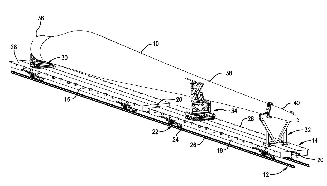
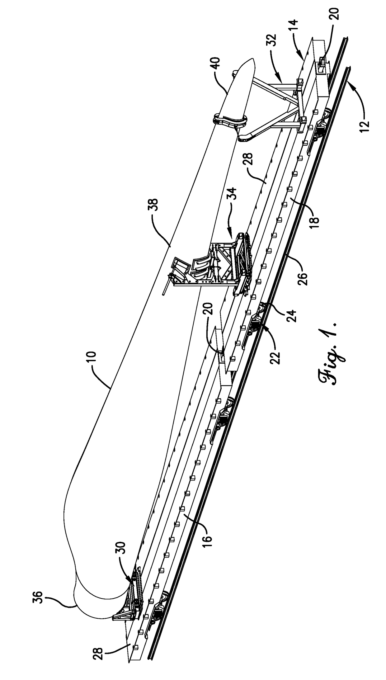
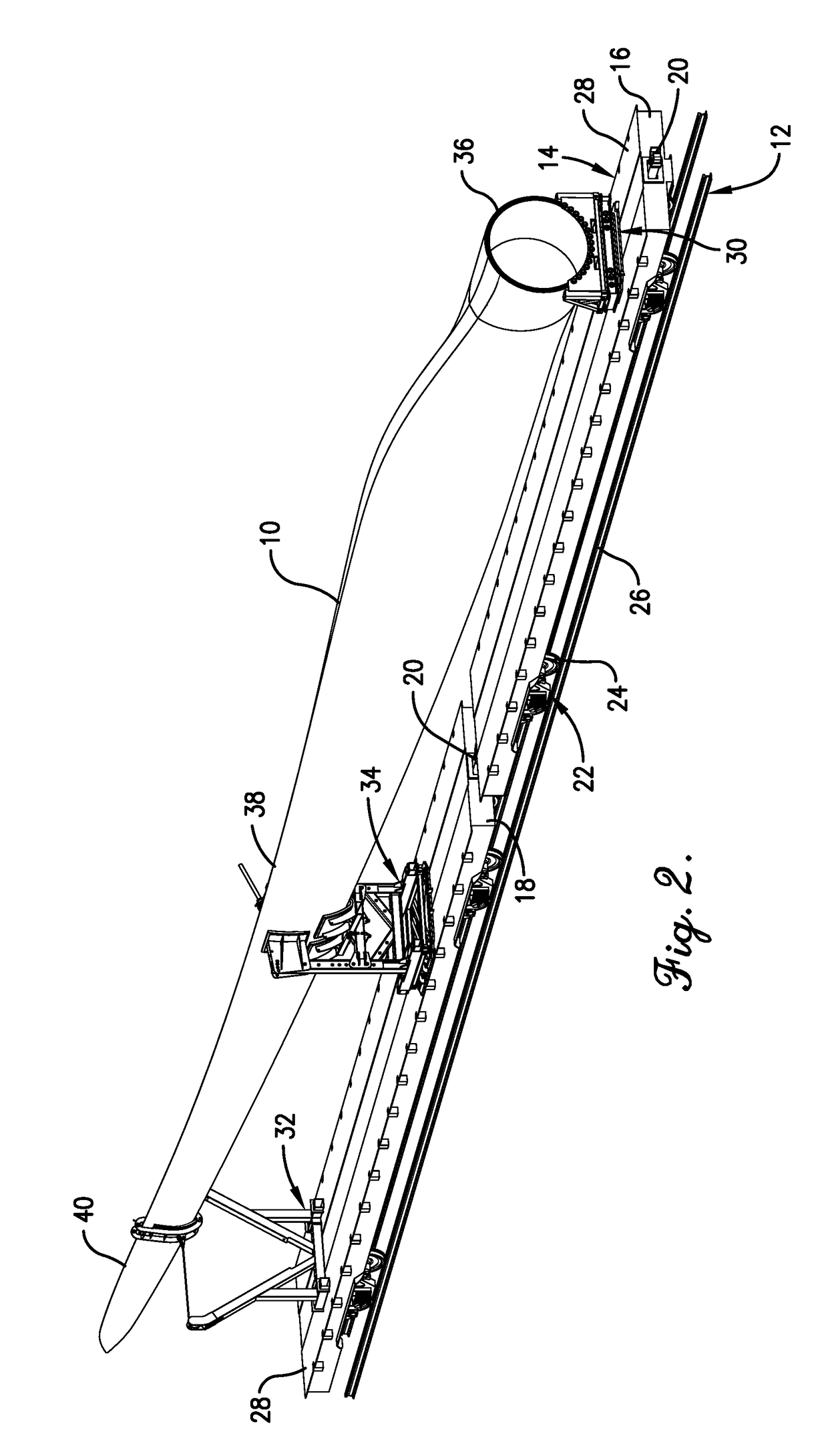
[0033]Turning now to the drawings in greater detail and initially to FIGS. 1 and 2, a transport system for conveying a wind turbine blade 10 along a railroad 12 is designated generally by the numeral 14. The transport system includes a first railcar 16 and an adjacent second railcar 18 that is connected to the first railcar 16 using couplers 20 positioned at the adjacent ends of the first and second railcars 16 and 18. Couplers 20 are normally also positioned at the opposite ends of the first and second railcars 16 and 18 so that they may be connected to other railcars that may be of the same or different construction. In one embodiment, each of the first and second railcars 16 and 18 is a flatcar that may be of conventional construction, comprising a pair of spaced apart trucks 22 that carry wheelsets 24 that ride along the rails 26 of the railroad 12 and an upper, generally flat platform 28 that is supported by the trucks 22. The first and second railcars 16 and 18 are pushed and / ...


PUM


Abstract

A transport system for transporting a wind turbine blade on first and second railcars that serve as load cars. A root end fixture on the first railcar is connected to a root end portion of the wind turbine blade. A mid-frame fixture on the second railcar supports a reinforced midsection of the wind turbine blade using a pair of support saddles. A tip end fixture restrains a tip end portion of the wind turbine blade against lateral movement outside of a preselected range of movement in opposite lateral directions and causing bending of the blade about the mid-frame fixture when the restraint device imparts sufficient restraining force to the tip end portion of the blade.

Description

RELATED APPLICATION[0001]This application is a continuation of U.S. application Ser. No. 15 / 426,834 filed Feb. 7, 2017, with the above-identified application being incorporated by reference herein in its entirety.BACKGROUND OF THE INVENTION[0002]The present invention relates generally to the transportation of items on a railroad and, more particularly, to fixtures used to transport wind turbine blades on railcars for travel on the railroad and methods of supporting the wind turbine blades during such transport.[0003]Wind farms employing large numbers of wind turbines to generate electricity have become increasingly popular alternative energy sources. The wind turbine blades, towers, hubs, nacelles and other components are normally transported separately by cargo ship, truck, and / or railcar from their manufacturing sites to the wind farms where they are assembled to form the operational wind turbines.[0004]As wind turbines continue to grow in height and blade length, challenges have ...

Claims


Application Information

Patent Timeline
Patent Type & Authority Applications(United States)
IPC IPC(8): F03D13/40B61D3/16B61D45/00F03D1/06B60P3/40
CPCF03D13/40B61D3/16F05B2240/941F03D1/0675B60P3/40B61D45/00Y02E10/72B60P7/12B61D45/001B61D3/166B61D45/003B61D45/008B60P1/649B60P1/6409
Inventor FLETCHER, SCOTT R.GLOVER, JOHN D.
Owner MARTIN BENCHER USA LLC
Why Eureka
Try Eureka