
Electro-optical device and electronic apparatus

a technology of electronic equipment and electro-optical devices, which is applied in the direction of non-linear optics, instruments, optics, etc., can solve the problems of reducing the heat dissipation of the drive ic, affecting the display quality or reliability of the electro-optical device, and taking a lot of labor and time. , to achieve the effect of convenient and proper provision of heat dissipation plate portions, small size and high definition

Active Publication Date: 2018-08-09
SEIKO EPSON CORP
View PDF0 Cites 8 Cited by
  • Summary
  • Abstract
  • Description
  • Claims
  • Application Information

AI Technical Summary

Benefits of technology

The invention provides an electro-optical device with heat dissipation plates on both sides of multiple mounting substrates that offer high definition, small size, and reliability. Additionally, an electronic apparatus that includes this device is also provided.

Problems solved by technology

Heat generated by a drive IC increases in accordance with high definition, which may affect display quality or reliability of an electro-optical device.
However, in the electro-optical device described in JP-A-2010-102219, it is necessary for a plurality of mounting substrates in an overlapped state to pass through the inside of a rectangular cylindrical heat dissipation member in an assembly process, and thereby, there is a problem that it takes much labor and time.
In addition, in order for the plurality of mounting substrates in an overlapped state to pass through the inside of the rectangular cylindrical heat dissipation member, it is necessary to provide a sufficient space between the mounting substrate and the rectangular cylindrical heat dissipation member, and thereby, there is a problem that heat dissipation from the drive IC is reduced.
In this case, it is possible to shorten an expensive flexible wiring substrate used for a mounting substrate.

Method used


Image

  • Electro-optical device and electronic apparatus
  • Electro-optical device and electronic apparatus
  • Electro-optical device and electronic apparatus

Examples


Embodiment Construction

[0030]Embodiments of the invention will be described with reference to the drawings. In the drawings referred to in the following description, the respective members are scaled differently from each other and the number of members is reduced so as to reduce each member and the like to a recognizable extent on the drawings. Hereinafter, each direction is represented by using an orthogonal coordinate system configured by the x axis, the y axis, and the z axis.

Configuration of Electro-Optical Device 1

Basic Configuration

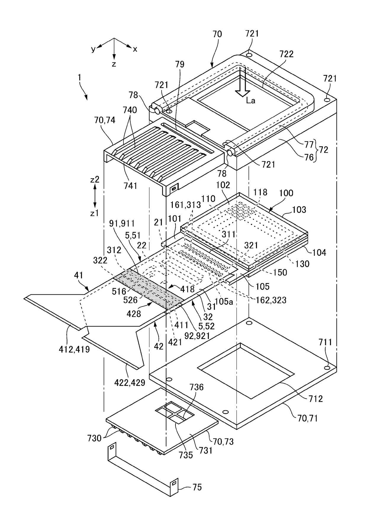
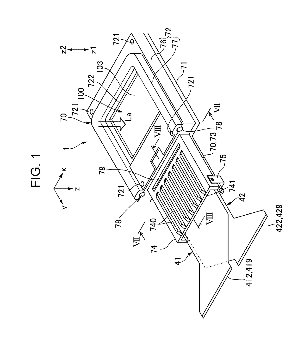
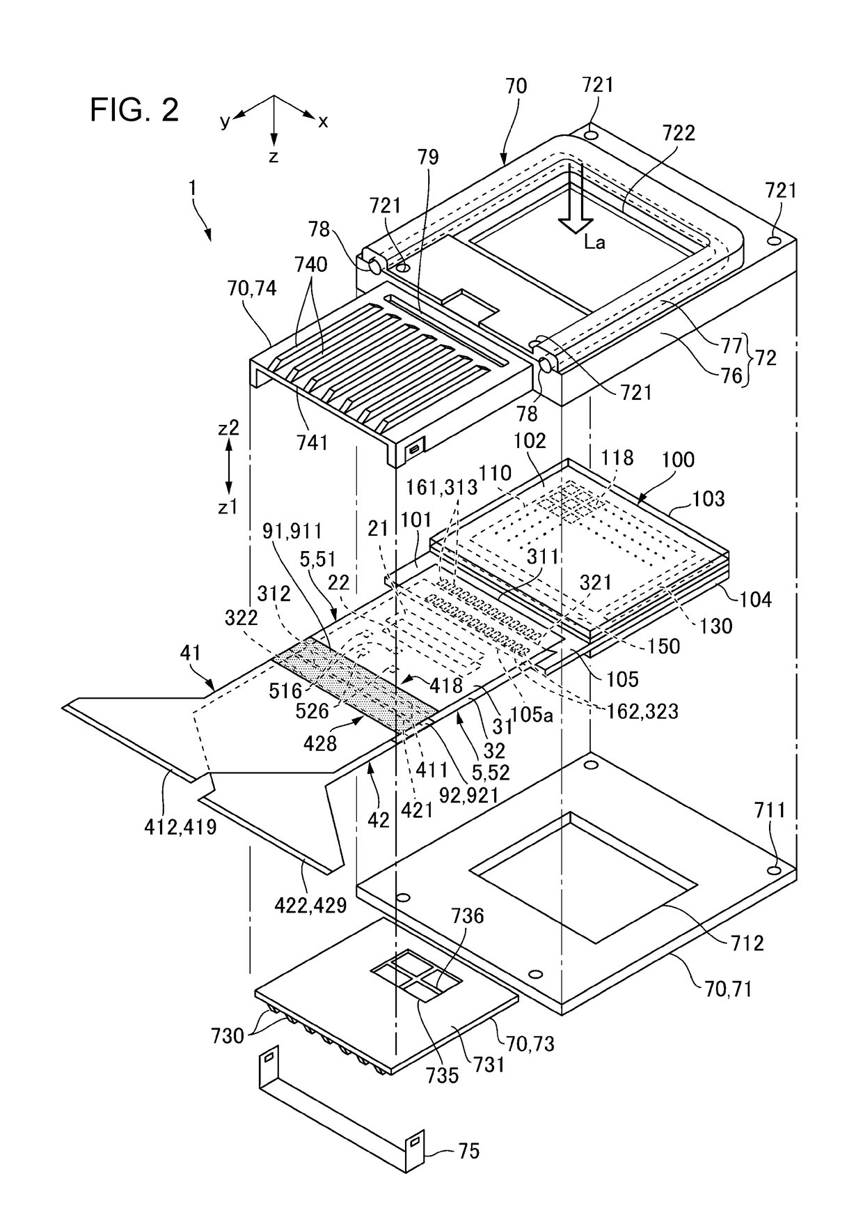
[0031]FIG. 1 is an explanatory view schematically illustrating a state where one aspect of an electro-optical device 1 to which the invention is applied is viewed in an oblique direction. FIG. 2 is an exploded perspective view in a state where a holder 70 is removed from an electro-optical panel 100, in the electro-optical device 1 illustrated in FIG. 1. FIG. 2 illustrates a few terminals and a few wires. In addition, in FIG. 2, terminals for connecting a drive IC to a f...


PUM

PropertyMeasurementUnit
flexibleaaaaaaaaaa
thicknessaaaaaaaaaa
dimensionsaaaaaaaaaa

Abstract

An electro-optical device includes a plurality of mounting substrates connected to an electro-optical panel. A holder includes a first holder member and a second holder member that support an electro-optical panel from both sides. In addition, a holder includes a first heat dissipation plate portion and a second heat dissipation plate portion on both sides of a part where a first drive IC and a second drive IC are mounted, among a part where a plurality of mounting substrates overlap each other and extend. A second heat dissipation plate portion is configured integrally with a second holder member, and a first heat dissipation plate portion is configured separately from a first holder member and a second heat dissipation plate portion and is fixed to a second heat dissipation plate portion by a fixing unit such as a fixing member or the like.

Description

BACKGROUND1. Technical Field[0001]The present invention relates to an electro-optical device including an electro-optical panel to which a wiring substrate is connected, and an electronic apparatus.2. Related Art[0002]An electro-optical device such as a liquid crystal device or an organic electroluminescence device may adopt a structure in which a plurality of mounting substrates including a drive IC mounted on a flexible wiring substrate are connected to one side of an electro-optical panel along with high definition, miniaturization, and the like. In addition, in order to dissipate heat generated by the drive IC, a structure has been proposed in which among parts where a plurality of mounting substrates overlap and extend, a part where the drive IC is mounted passes through the inside of a rectangular cylindrical heat dissipation member (refer to JP-A-2010-102219).[0003]Heat generated by a drive IC increases in accordance with high definition, which may affect display quality or r...

Claims


Application Information

Patent Timeline
Patent Type & Authority Applications(United States)
IPC IPC(8): G02F1/1333G02F1/1345
CPCG02F1/133385G02F1/13452G02F1/133308G02F1/13454
Inventor MIYASHITA, TOMOAKI
Owner SEIKO EPSON CORP
Learn More