Method for modifying an onboard control system of a pool cleaner, and power source for a pool cleaner

a technology for swimming pool cleaners and control systems, which is applied in the direction of vehicle sub-unit features, process and machine control, instruments, etc., can solve the problems of affecting the operation of the swimming pool cleaner, the specific circumstances of the user, and the time-consuming remote control of the user

Inactive Publication Date: 2018-08-09
ZODIAC POOL SYST LLC
View PDF0 Cites 9 Cited by
  • Summary
  • Abstract
  • Description
  • Claims
  • Application Information

AI Technical Summary

Benefits of technology

[0025]One advantage of the present invention is that there is no pre-established link between the availability of the power source and the availability of the pool cleaner, in terms of the availability to receive data from an external device or system such as a user terminal. The availability of the pool cleaner can depend on many circumstances related to its use, for example, use in different swimming pools, maintenance operations, etc. The power source can often be available for receiving setup data even when the pool cleaner as such is not available. Thereby, at least a first part of a process of modifying the setup of the onboard control system of a pool cleaner can be carried out without the pool cleaner as such being available, by transferring the relevant setup data to the power source and, if necessary, by storing the setup data there. The modification process can then be completed once the pool cleaner becomes available, and / or following a trigger action by the user, whereby the user authorizes or triggers completion of the process.
[0026]In some embodiments of the invention, the pool cleaner comprises a housing, drive means or a drive mechanism including wheels and / or tracks, at least one electrically driven motor, at least one pump for pumping water from at least one inlet to at least one outlet through at least one filter for retaining debris. In some embodiments, the onboard control system, the motor, the pump and the filter are arranged within the housing. In some embodiments, the same motor is used for driving the pump and the drive means. In other embodiments, different motors are used for driving drive means or drive mechanism and the pump.
[0027]In some embodiments, the onboard control system is operatively connected to at least one orientation and / or position sensor. The sensor can be selected from a list including magnetometers, accelerometers, angular rate sensors, tilt sensors, proximity sensors, motion sensors, or any combination thereof.
[0028]In some embodiments, for the purpose of determining the orientation of the pool cleaner, an accelerometer is used to measure tilt angle about three axes.
[0029]In some embodiments, the pool cleaner comprises an angular rate sensor, commonly known as a gyro. Based on the output from such a sensor, the onboard control system can, by integrating the rate and elapsed time, compute an estimate of the orientation and / or position of the pool cleaner.
[0030]In some embodiments, the pool cleaner includes at least one proximity sensor, the output of which can be used by the onboard control system to determine the proximity of the pool cleaner to a substantially vertical surface of the pool.

Problems solved by technology

However, this setup may not always be optimal in view of the specific circumstances of a particular user, for example, in view of a specific shape and / or size of the swimming pool, in view of the characteristics of debris that is to be removed, the amounts thereof, etc.
However, remote control by the user himself or herself is time-consuming for the user and may indeed be suboptimal in terms of efficiency.
However, wireless communication with a swimming pool cleaner operating at the bottom of a swimming pool can sometimes be problematic, and US-2014 / 0303810-A1 does not explain how to deal with these problems.

Method used


Image

  • Method for modifying an onboard control system of a pool cleaner, and power source for a pool cleaner
  • Method for modifying an onboard control system of a pool cleaner, and power source for a pool cleaner
  • Method for modifying an onboard control system of a pool cleaner, and power source for a pool cleaner

Examples


Embodiment Construction

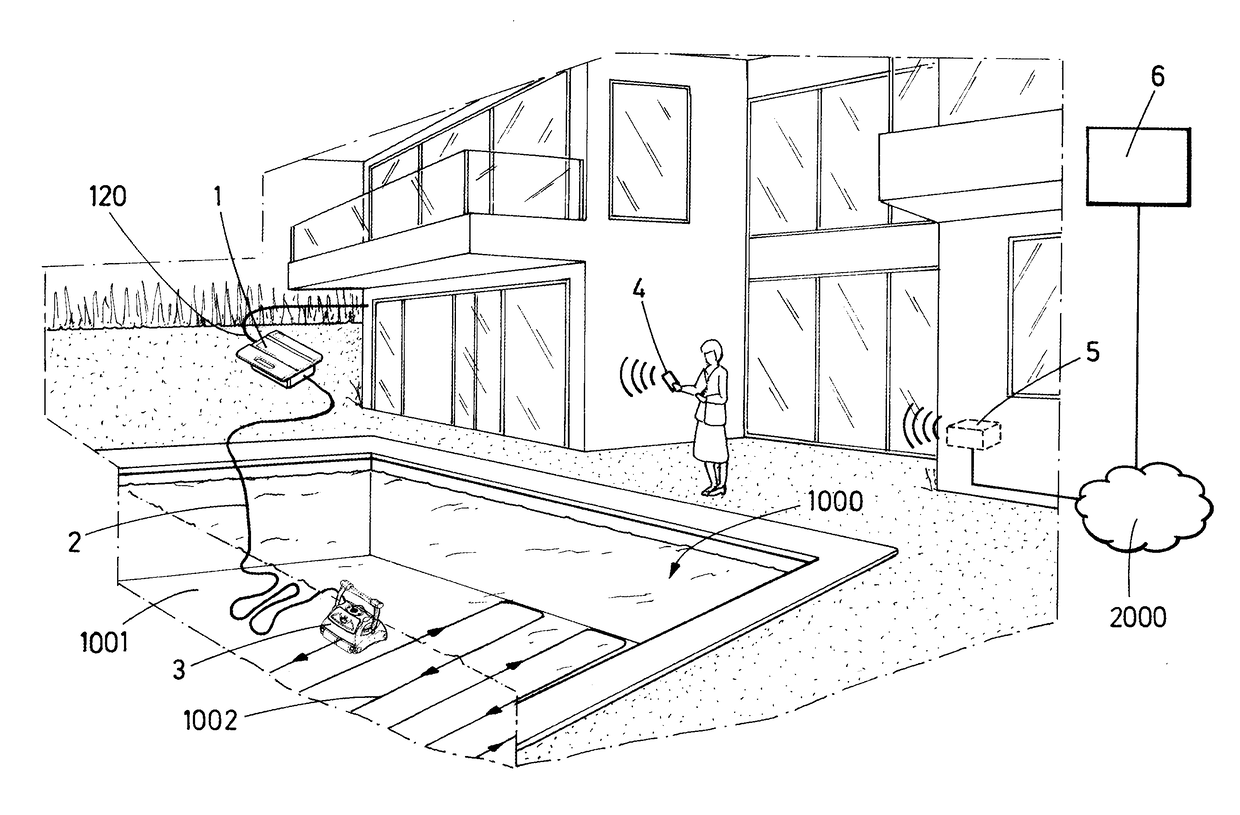
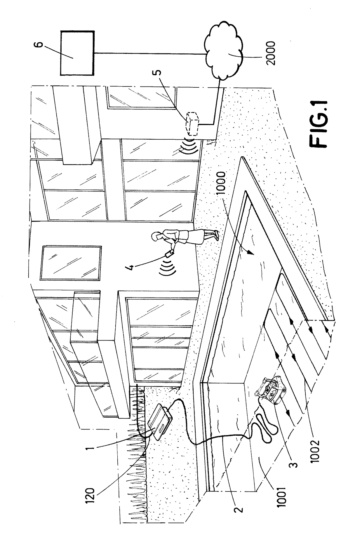
[0074]FIG. 1 illustrates a pool cleaner 3 moving on the bottom surface 1001 of a swimming pool 1000, following a path 1002. The pool cleaner receives electrical power from a remote power source 1 via a power cable 2. The power source 1 is, in this embodiment, a pool side power source placed a couple of meters from the edge of the swimming pool, and connected to an external power grid via a cable 120. That is, the power source 1 is connected to the pool cleaner 3 by one cable 2 and to the power grid by another cable 120. The power source 1 comprises, in the illustrated embodiment, a communication module or means for wireless communication with a user terminal 4 such as smartphone or tablet computer. The user terminal 4 is provided with its own a communication module or means for wireless communication with a local communication node 5, through which the terminal 4 can establish communication with a remote computer or computer system 6, over a network 2000.

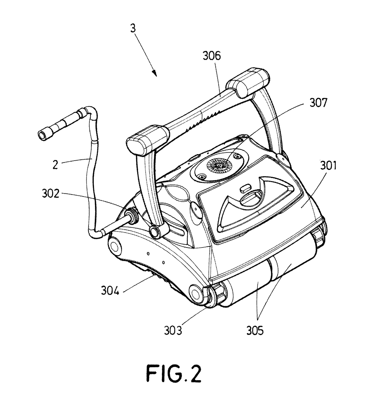
[0075]FIG. 2 shows how, in t...


PUM


Abstract

An onboard control system of an electrically powered pool cleaner (3) is disclosed. The disclosed system is configured to operate the pool cleaner in accordance with a setup (A, B, C) of the onboard control system (350). The pool cleaner is configured for receiving electrical power via a cable (2) connecting the pool cleaner (3) to a power source (1). A method for operating an automatic pool cleaner with segmented cleaning setup data is also disclosed and includes determining that the automatic pool cleaner is disposed in a particular segment of a pool based on outputs from one or more onboard sensors; and controlling movement of the automatic pool cleaner along a surface of the pool based on the determining so that the automatic pool cleaner spends a predetermined amount of time in the particular segment of the pool.

Description

CROSS-REFERENCE TO RELATED APPLICATIONS[0001]This application claims benefit to and is a continuation-in-part of U.S. patent application Ser. No. 15 / 095,398, filed Apr. 11, 2016, and entitled “Method For Modifying An Onboard Control System Of A Pool Cleaner, And Power Source For A Pool Cleaner,” the disclosure of which is incorporated herein by reference in its entirety.TECHNICAL FIELD[0002]The invention relates to the field of swimming pool cleaners, especially electrically powered robotic swimming pool cleaners arranged for movement on and cleaning of the surface of a swimming pool, including the bottom surface of the swimming pool and optionally wall surfaces of the swimming pool.BACKGROUND OF THE INVENTION[0003]Electrically driven robotic swimming pool cleaners are well known in the art. Such cleaners generally include a power supply, typically an onboard battery and / or an external power source, often in the form of a portable power source device, placed in the vicinity of the s...

Claims


Application Information

Patent Timeline
Patent Type & Authority Applications(United States)
IPC IPC(8): G05D1/02E04H4/16G05D1/00
CPCG05D1/0206E04H4/1654G05D1/0016G05D1/0022G05D2201/0203B60Y2200/40B60Y2400/301B60Y2410/115B60Y2400/604B60Y2400/214B60Y2306/15G05D1/027
Inventor DURVASULA, KAMESHWARHANAN, ETHANSMAGIN, VLADIMIR
Owner ZODIAC POOL SYST LLC
Why Eureka
Try Eureka