
Radio base station, user terminal and radio communication method

a radio communication method and user terminal technology, applied in the field of radio communication methods, can solve the problems of limited spectra of licensed bands, and achieve the effect of improving spectral efficiency

Active Publication Date: 2018-08-09
NTT DOCOMO INC
View PDF7 Cites 8 Cited by
  • Summary
  • Abstract
  • Description
  • Claims
  • Application Information

AI Technical Summary

Benefits of technology

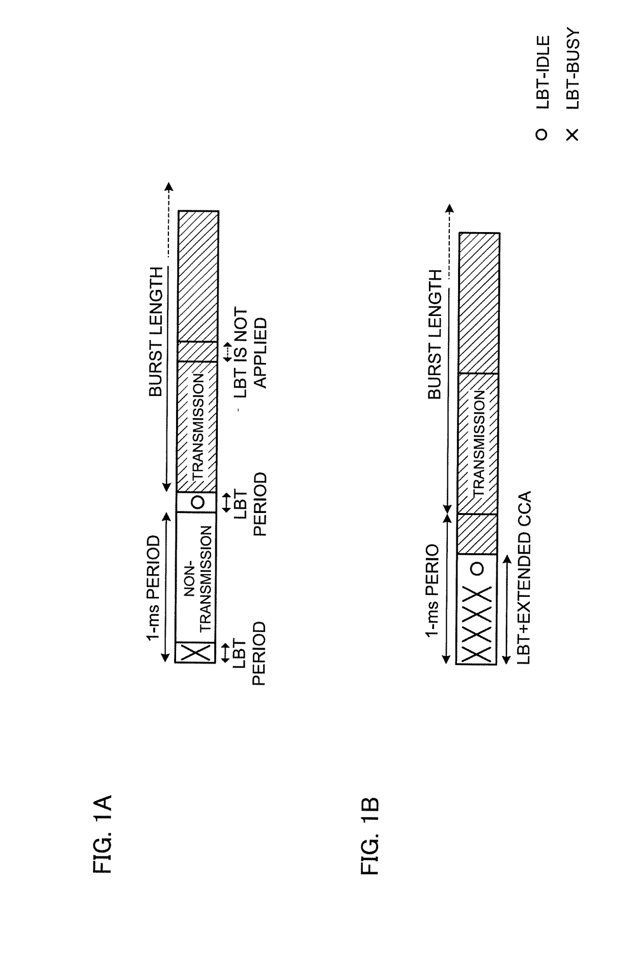
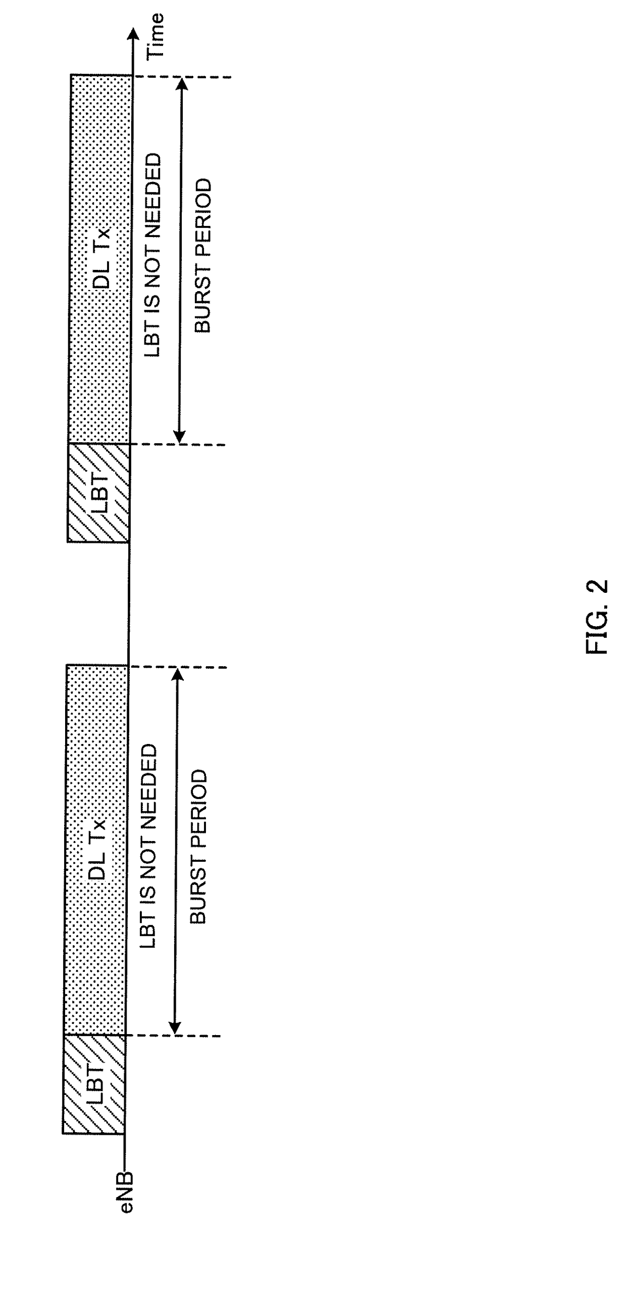
The present invention provides a way to allow LTE systems to co-exist with other systems, such as Wi-Fi, and with other LTE operators. This co-existence can be facilitated by implementing "listening" as an interference control function. Additionally, the invention improves spectral efficiency in cells that use pre-transmission listening, such as unlicensed bands. This means that LTE systems can more efficiently use the available spectrum in these bands.

Problems solved by technology

Although more frequency bands need to be added to meet this increasing user traffic, licensed bands have limited spectra (licensed spectra).

Method used


Image

  • Radio base station, user terminal and radio communication method
  • Radio base station, user terminal and radio communication method
  • Radio base station, user terminal and radio communication method

Examples


first example

[0053]A case will be described with a first example where the CW size is controlled based on the number of NACKs in response to data that is included in burst transmission after listening. Note that DTX may be included in the number of NACKs, or the CW size may be controlled based on the number of ACKs, instead of the number of NACKs.

[0054]FIG. 4 is a diagram to show an example of DL transmission to which listening is applied. FIG. 4 shows a case where burst DL transmission of maximum 4 ms is configured when the result of listening shows the idle state. The duration of burst DL transmission is not limited to 4 ms and can be configured as appropriate.

[0055]According to the present embodiment, (1) the number of subframes in bursts in which the number of NACKs is counted (L subframes), (2) the cycle of bursts to count the number of NACKs (M bursts), and (3) a threshold number of NACKs (N) for deciding to expand the CW size can be configured as parameters for controlling the change of t...

second example

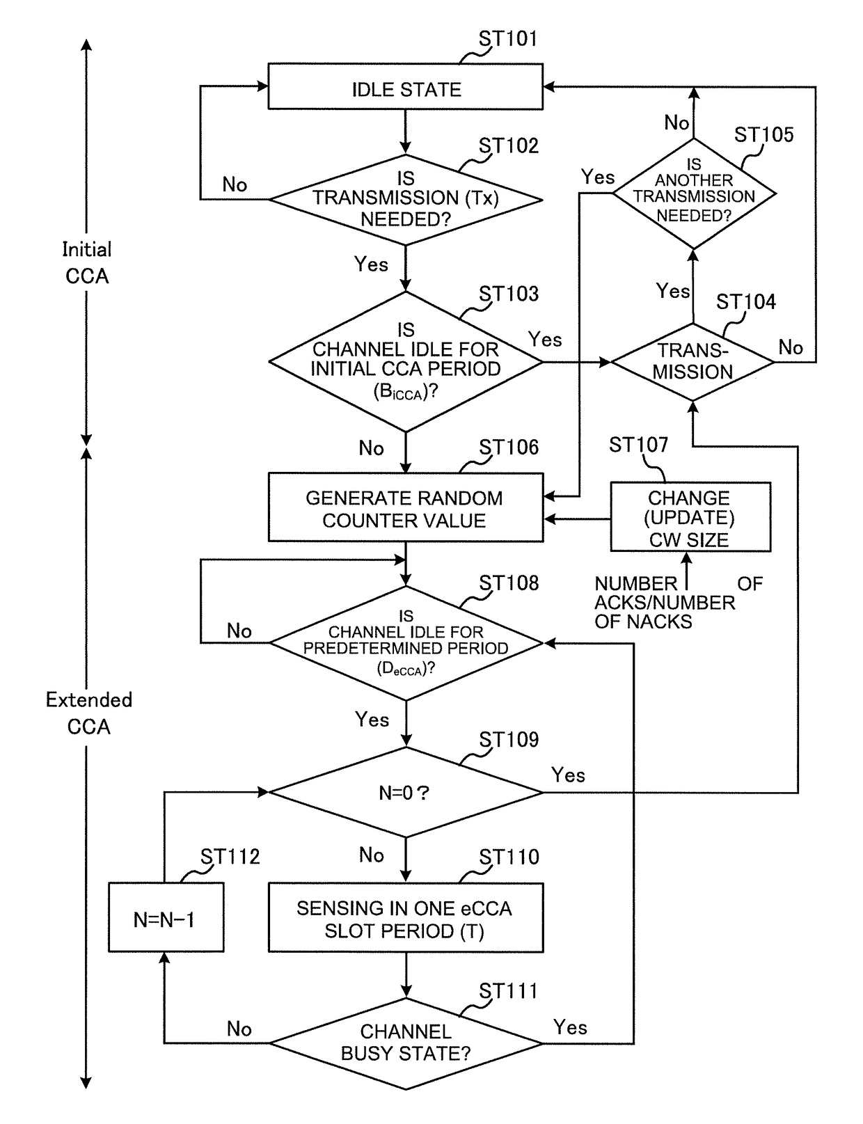
[0075]An example of the method of controlling the CW size in listening prior to DL transmission will be described with a second example. FIG. 6 shows an example of the listening operation according to the second example. Note that the following CW size control method can be applied to UL LBT (user terminal) as well.

[0076]When starting transmission from the idle state (which is, for example, the state the radio base station's buffer is empty) (ST101 and ST102: Yes), sensing is conducted in the initial LBT (CCA) period BiCCA (ST103). The initial LBT (CCA) period BiCCA may be, for example, 34 μs. If the result of sensing shows that a channel is available (idle state) (ST103: Yes), DL transmission is made (ST104).

[0077]If the initial CCA sensing shows that no channel is available (busy state) (ST103: No), or if transmission needs to be made for reasons other than that the idle state is assumed (for example, because there is another data transmission after ST104 (ST105: Yes)), random bac...


PUM


Abstract

The present invention is designed to allow co-presence with other systems, and, furthermore, achieve improved spectral efficiency in cells (for example, unlicensed bands) in which pre-transmission listening is employed. The present invention provides a transmission section that transmits a DL signal, a control section that performs listening before the DL signal is transmitted, and controls DL transmission, and a receiving section that receives a delivery acknowledgement signal (ACK / NACK) in response to the DL transmission, and the control section controls a contention window size to apply to listening based on the number of NACKs in response to a predetermined period of DL transmission.

Description

BACKGROUNDTechnical Field[0001]The present invention relates to a radio base station, a user terminal and a radio communication method in next-generation mobile communication systems.Background Art[0002]In the UMTS (Universal Mobile Telecommunications System) network, the specifications of long term evolution (LTE) have been drafted for the purpose of further increasing high speed data rates, providing lower delays and so on (see non-patent literature 1). The specifications of LTE-advanced (Rel. 10 to 12) have been drafted for the purpose of achieving further broadbandization and higher speeds beyond LTE, and, in addition, for example, a successor system of LTE—referred to as “5G” (5th generation mobile communication system)—is under study.[0003]In LTE of Rel. 8 to 12, the specifications have been drafted assuming exclusive operations in frequency bands that are licensed to operators—that is, licensed bands. As licensed bands, for example, 800 MHz, 2 GHz and / or 1.7 GHz are used.[000...

Claims


Application Information

Patent Timeline
IPC IPC(8): H04L1/16H04W72/08H04L1/18
CPCH04L1/1657H04W72/082H04L1/1812H04W16/14H04W28/04H04W74/0808H04L1/1867H04L1/187H04W72/54H04W72/541
Inventor HARADA, HIROKINAGATA, SATOSHI
Owner NTT DOCOMO INC
Learn More