Module attachment device

Active Publication Date: 2018-08-16
PANASONIC INTELLECTUAL PROPERTY MANAGEMENT CO LTD
View PDF7 Cites 0 Cited by
  • Summary
  • Abstract
  • Description
  • Claims
  • Application Information

AI Technical Summary

Benefits of technology

[0007]The module attachment device according to one aspect of the present disclosure has a comp

Problems solved by technology

However, the metal attachment hardware disclosed in Japanese Unexamined Patent Application Publication No.
Accordingly, this technique

Method used


Image

  • Module attachment device
  • Module attachment device
  • Module attachment device

Examples


Example

Embodiment 1

[0029]A description will be given of passenger operation device 100 according to Embodiment 1 of the present disclosure with reference to FIGS. 1 to 12.

[1-1. Overall Configuration]

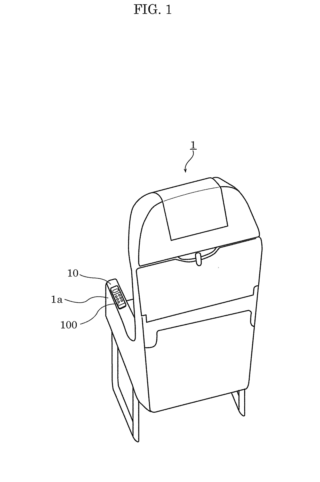
[0030]FIG. 1 is a perspective view showing an example of a seat installed in a passenger cabin of an aircraft.

[0031]Passenger operation device 100 is provided embedded in mounting surface 10a of plate-like member 10 that constitutes an upper portion of arm rest 1a of seat 1 that is one of a plurality of seats installed in a passenger cabin of an aircraft. That is, mounting surface 10a is an upper surface of arm rest 1a of seat 1. Passenger operation device 100 is an example of a module attachment device. A passenger seated in seat 1 can use an entertainment system installed in the passenger cabin of the aircraft or call a cabin attendant by operating passenger operation device 100 installed in arm rest 1a.

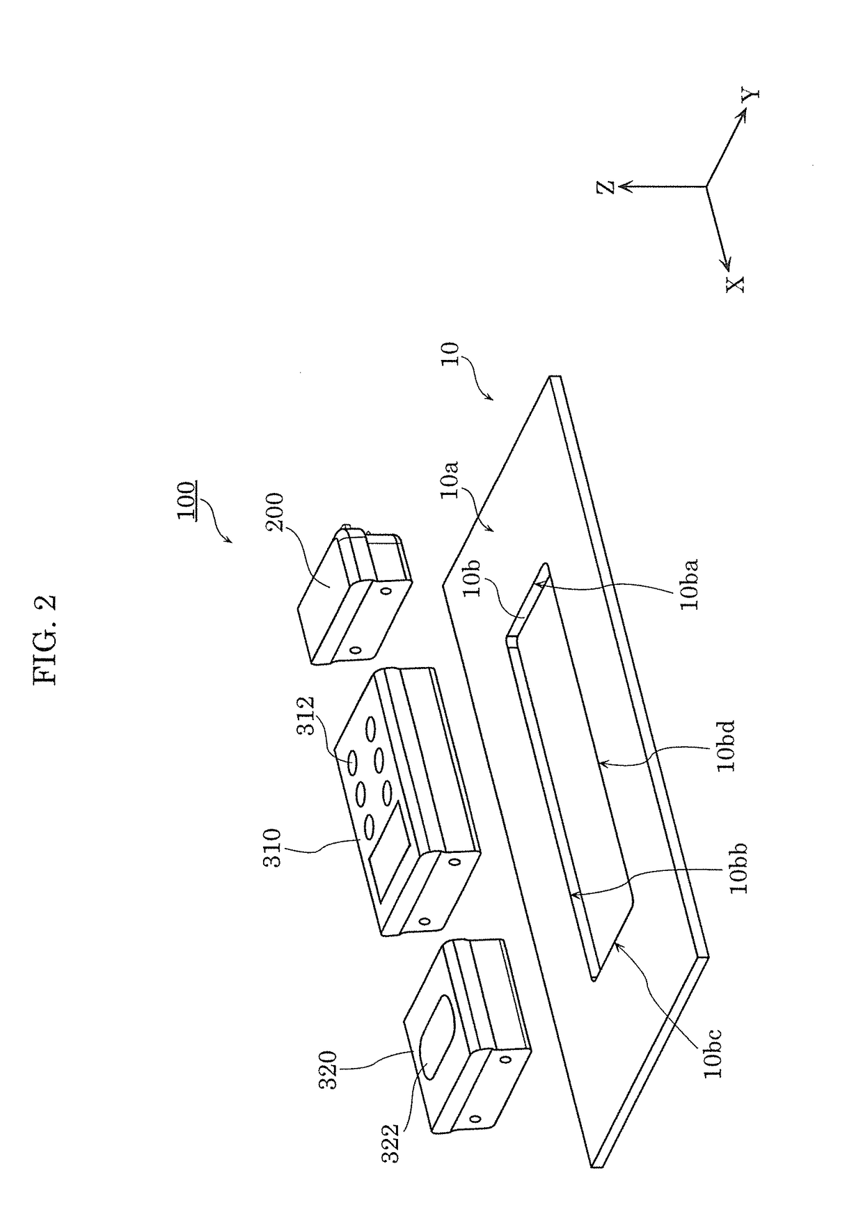
[0032]FIG. 2 is an exploded perspective view of passenger operation device 100.

[0033]As s...

Example

Embodiment 2

[0098]Next, passenger operation device 100A according to Embodiment 2 will be described with reference to FIGS. 13 and 14.

[2-1. Configuration]

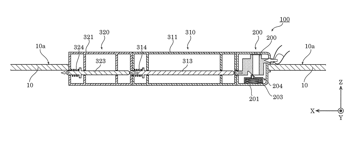
[0099]FIG. 13 is a diagram showing a cross section of a passenger operation device according to Embodiment 2, the cross section corresponding to the VI-VI cross section taken along a plane parallel to ZX plane. FIG. 14 is an enlarged view of the cross section of passenger operation device 100A shown in FIG. 13, showing the vicinity of coupling module 400.

[0100]Passenger operation device 100A is different from passenger operation device 100 according to Embodiment 1 in that passenger operation device 100A includes coupling module 400 in addition to coupling module 200, operation button module 310, and connector module 320. That is, coupling module 200, operation button module 310, and connector module 320 of passenger operation device 100A have the same configurations as those of coupling module 200, operation button module 310, and...


PUM


Abstract

A module attachment device includes: a first module that includes a first casing and a first moving member, the first moving member being configured such that when a first end is pushed, a second end protrudes from the first casing; and a second module that is engaged with a mounting surface, and includes a second moving member that is disposed at a position where the second moving member is capable of pushing the first end of the first moving member, wherein in response to the first end of the first moving member being pushed by the second moving member, the second end of the first moving member protruding from the first casing comes into engagement with the mounting surface.

Description

CROSS REFERENCE TO RELATED APPLICATION[0001]This application is a U.S. continuation application of PCT International Patent Application Number PCT / JP2017 / 004850 filed on Feb. 10, 2017, the entire content of which is hereby incorporated by reference.BACKGROUND1. Technical Field[0002]The present disclosure relates to a module attachment device.2. Description of the Related Art[0003]Japanese Unexamined Patent Application Publication No. H11-283141 discloses metal attachment hardware that attaches an embedded smoke detector base to a mounting surface such as a ceiling without a screwing operation.[0004]However, the metal attachment hardware disclosed in Japanese Unexamined Patent Application Publication No. H11-283141 is configured such that the surface to be embedded in the ceiling has a protruding configuration, which requires a large space enough to accommodate the metal attachment hardware on the back side of the mounting surface. Also, the use of a tool such as a driver is required...

Claims


Application Information

Patent Timeline
IPC IPC(8): F16B2/04B64D11/06
CPCF16B2/04B64D11/0646B64D11/00155
Inventor MURAKAMI, HIROYUKITAKETANI, KEIICHI
Owner PANASONIC INTELLECTUAL PROPERTY MANAGEMENT CO LTD
Why Eureka
Try Eureka