Image processing unit, image processing method, and projection system

Active Publication Date: 2018-08-16
SONY CORP
View PDF5 Cites 3 Cited by
  • Summary
  • Abstract
  • Description
  • Claims
  • Application Information

AI Technical Summary

Benefits of technology

[0005]In recent years, ultra-short-focus projectors have been developed. An ultra-short-focus projector is installable in proximity to the screen, and is able to perform projection from a close range, unlike a vertical projection type projector. In a case where the above-described correction processing for a projection screen is performed in the ultra-short-focus projector, an imaging unit may be mounted on a projector main body, in order to improve user convenience during imaging of the projection screen. However, in a case where the imaging unit is mounted on the projector main body in the ultra-short-focus projector, it may not be possible to image the entire projection screen that should be imaged and is necessary for calibration, depending on a limit on an imaging angle of view of the imaging unit, or dependi

Problems solved by technology

However, in a case where the imaging unit is mounted on the projector main body in the ultra-short-focus projector, it may not be possible to image the entire projection screen that should be imaged and is necessary for calibration, depending on a limit on an imaging angle of view of the imaging unit, or depending on a distance between the imaging unit and a screen, thus allowing for imaging of only a portion thereof.
In that case, it is difficult to carry out calibration of a projected image.
There is also a case where it is possible to image a necessary entire projection screen, by performing imaging using a camera such as a fish-eye camera having a wide imaging angle of view, but a wide angle camera is expensive and large.
Hence, a sale of a

Method used


Image

  • Image processing unit, image processing method, and projection system
  • Image processing unit, image processing method, and projection system
  • Image processing unit, image processing method, and projection system

Examples


Example

MODIFICATION EXAMPLE

[0075]In the procedure illustrated in FIG. 3, the procedure of the projection and the imaging of the image including the first image pattern 31 and the procedure of the projection and the imaging of the image including the second image pattern 32 are performed separately, but these procedures may be collectively performed. For example, it is possible to perform the above-described procedures collectively, by projecting a mixture pattern 35 in which the first image pattern 31 and the second image pattern 32 are mixed, as illustrated in FIG. 13.

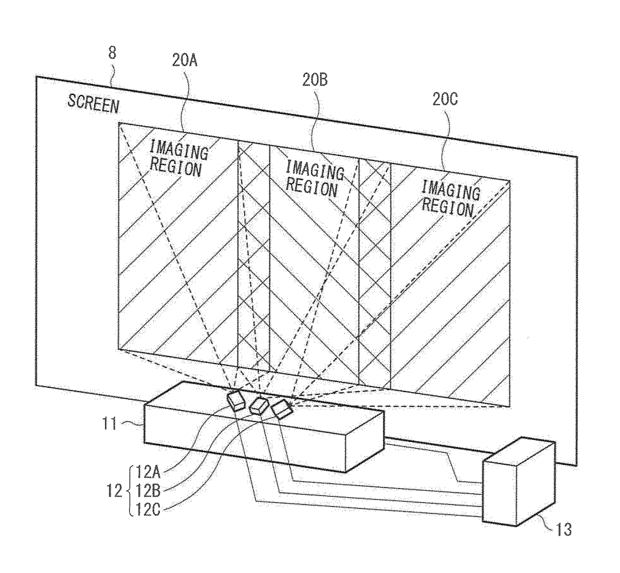
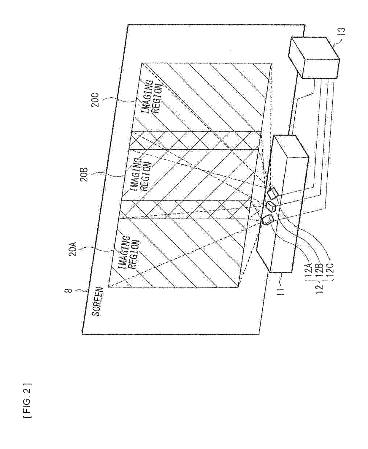
[0076]Further, it is also possible to obtain an image that imitates an imaging position other than the front of the screen 8, by subjecting projection transformation such as keystone correction to an image after stitching. Furthermore, in the configuration example of FIG. 2, the projector 11 is of the ultra-short-focus projection type, and the imaging position is in proximity to the screen 8; however, the technique based on ...


PUM


Abstract

An image processing unit of the disclosure includes an imaging section that acquires a plurality of partial images as a captured image, by imaging a projection screen provided by a projector through division of the projection screen into a plurality of regions to have partially overlapping imaging regions, and an estimation section that performs an operation a plurality of times on a basis of the captured image, the operation being performed to estimate a projection transformation matrix for linking of the partial images adjacent to each other.

Description

TECHNICAL FIELD[0001]The disclosure relates to an image processing unit that has a function of calibrating a projected image, an image processing method, and a projection system.BACKGROUND ART[0002]As an application for a projector, there is one type that performs correction processing for distortion and luminance unevenness of a projection screen. Further, as for a multi-projection system that combines a plurality of projection screens into one projection screen by linking the projection screens, there is one type that subjects a projected image to edge blending processing that makes a joint between a plurality of projection screens inconspicuous. To perform these kinds of correction processing for a projection screen, there is a technique of performing calibration of a projection image to be projected by a projector, by imaging a projection screen through use of an imaging unit, and then analyzing a captured image. For example, PTL 1 discusses a technique of imaging a projection s...

Claims


Application Information

Patent Timeline
IPC IPC(8): G06T3/40H04N9/31
CPCG06T3/4038H04N9/3185H04N9/3147G06T2200/32G09G3/002H04N9/3194G06F3/1446G09G2300/026G09G2310/0232G09G2320/0693G09G2360/16G03B35/20H04N23/698
Inventor FUKUI, KENICHI
Owner SONY CORP
Why Eureka
Try Eureka