Eureka AIR delivers breakthrough ideas for toughest innovation challenges, trusted by R&D personnel around the world.

Distributor with at least two distributor disks with variable speed

Inactive Publication Date: 2018-08-23
RAUCH LANDMASCHFAB
View PDF3 Cites 2 Cited by
  • Summary
  • Abstract
  • Description
  • Claims
  • Application Information

AI Technical Summary

Benefits of technology

The invention is a simple and cost-effective way to improve a distributor that allows for variable speed control of distributor disks. This allows for effective spreading along edges and borders, as well as in wedges. The invention also guarantees a continuous change in the speed of one or more distributor disks.

Problems solved by technology

The drawback of such distributors, which are unpowered themselves and are driven simply mechanically by means of the power take-off shaft, is, however, mainly the lack of adaptability or the insufficient adaptability to different operating conditions, for example, the coverage of greater working widths, the lack of the possibility of adjusting to different, smaller working widths as well as the insufficient adaptation to different types of de-icing salts and types of distribution, such as normal spreading, border spreading or spreading along edges or also for switching to partial widths, such as the spreading of field wedges and the like.
However, said measures represent a great work effort for the operator and require, moreover, corresponding care.
However, they lead, especially at the border of the field, where material is spread on one side only and there is consequently no overlap, to underspreading if material is spread to the border of the field only, or to spreading beyond the field border and hence to corresponding losses of fertilizer.
All these solutions have the drawback that an interruption in the spreading operation is necessary and the farmer must leave the tractor to carry out the corresponding adjustments.
In many cases, this adjustment is not carried out because of the time and work effort needed, with the result that not enough material will be spread on the strip at the edge or material will be spread beyond the edge.
These methods are, however, extremely inaccurate and especially not variable enough.
Prior-art variable-speed gears for this purpose are, however, very complicated and expensive and their production cost is therefore practically the same as that of single hydraulic drives (EP 0 330 839 A1), by means of which the task of spreading along edges can be solved in a comfortable manner, but which are too expensive for many farms, and whose function is, as a rule, also rather unreliable.
This is likewise complicated and costly, especially since the gears are provided in pairs.
Aside from the fact that the design of the prior-art gear is very complicated and therefore expensive, a continuous speed change of at least one of the two distributor disks is not possible, and the gear requires a very large space for its installation, which is available in distributors of this class only with limitations.
However, the solutions proposed in this document have not yet reached the production stage because of technical problems.
Thus, on the one hand, especially the hydraulic transmissions provided with hydraulic motors have proved to be unreliable in terms of function and require maintenance.
On the other hand, the mechanical transmissions have also proved not to be sufficiently suitable for practical applications, because the belt drives used for this purpose are susceptible to wear and do, moreover, require space for their installation, which requires conversion of the entire drive train of the distributor disks.
If the bevel or miter gear connecting the carrier shaft of the distributor disk to the cross shaft is formed by a friction gear, in which the friction gears that are in contact with one another can be displaced in relation to one another into different radial positions by means of actuators, the speed change brought about hereby is found to be relatively small, and the wear, which leads to the need for maintenance, also proved to be relatively great.

Method used


Image

  • Distributor with at least two distributor disks with variable speed
  • Distributor with at least two distributor disks with variable speed
  • Distributor with at least two distributor disks with variable speed

Examples


Embodiment Construction

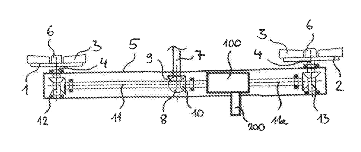
[0056]Referring to the drawings, the terminal or output-side section of the drive train of the distributor disks 1, 2 of a distributor in the form of a twin disk fertilizer spreader, which is not shown in more detail, which section is shown in FIG. 1, has the two distributor disks 1, 2, which are arranged in laterally spaced locations from one another and which are equipped each with throwing blades 3. The distributor disks 1, 2 are driven with opposite directions of rotation, and they rotate in this case opposite the direction of travel from the inside to the outside. Each distributor disk 1, 2 is seated non-rotatably and especially replaceably on an approximately vertical carrier shaft 4, which is mounted in a housing 5. A hub 6 arranged at the free end of each carrier shaft 4 is provided for fastening the throwing disks 4.

[0057]The distributor disks 1, 2 are located under a respective outlet (not shown) of a dispensing element, likewise not shown, which is, in turn, arranged unde...


PUM


Abstract

A distributor includes two distributor disks, which are driven rotatably by a drive train, to be attached to a power take-off shaft of a traction unit or of a tractor. The drive train includes a central input shaft driving a cross shaft to drive distributor disks via a central gear. The distributor disks can be rotated at different speeds with a reducing gear with variable output speed, arranged downstream of the central gear. The reducing gear is configured as a mechanical coaxial transmission with an input shaft connected to the cross shaft and an output shaft arranged coaxially to the cross shaft. A speed reduction ratio is changed by an adjusting element between a normal position, with an input speed of the input shaft corresponding to the output speed of the output shaft, and a speed reduction position with the input speed not equal to the output speed.

Description

CROSS REFERENCE TO RELATED APPLICATIONS[0001]This application is a United States National Phase Application of International Application PCT / EP2016 / 001562, filed Sep. 16, 2016, and claims the benefit of priority under 35 U.S.C. § 119 of German Application 10 2015 011 949.4, filed Sep. 18, 2015, the entire contents of which are incorporated herein by reference.FIELD OF THE INVENTION[0002]The present invention pertains to a distributor with at least two distributor disks, which are driven rotatably by a drive train that can be connected to a power take-off shaft of a traction unit or a tractor, wherein the drive train comprises a central input shaft, which drives a cross shaft used to drive a respective distributor disk via a central gear, wherein at least one of the distributor disks can be rotated by means of a reducing gear arranged downstream of the central gear with variable output speed at a speed different from that of the other distributor disks, wherein the reducing gear has ...

Claims


Application Information

Patent Timeline
IPC IPC(8): A01C17/00A01C19/04A01C15/16F16D25/10F16H3/00
CPCA01C17/005A01C19/045A01C15/16A01C17/008F16D25/10F16H3/006
Inventor ZEITVOGEL, THOMASSTOCKLIN, VOLKER
Owner RAUCH LANDMASCHFAB
Why Eureka
Eureka Blog
Learn More