Integrated visual geo-referencing target unit and method of operation

a geo-referencing target and integrated technology, applied in surveying and navigation, navigation instruments, instruments, etc., can solve the problems of reducing and affecting the accuracy of geo-referencing data. , the accuracy of a single image is often limited to +/2 m

Active Publication Date: 2018-08-23
PROPELLER AEROBOTICS PTY LTD
View PDF15 Cites 3 Cited by
  • Summary
  • Abstract
  • Description
  • Claims
  • Application Information

AI Technical Summary

Problems solved by technology

The challenge that exists is both turning raw imagery from aerial capture by, for example, a UAV, into valuable surveying and inspection outputs, and also in visualizing and using the information without needing to be technically trained in expensive geospatial or computer aided design software.
The ease of imagery capture has resulted in gigabytes of un-georeferenced imagery being uploaded by users.
Unfortunately, in order to accurately georeference this data, it is often necessary to hire a certified surveyor to capture ground control points, in addition to post processing the imagery to locate and identify the capture ground control points.
This normally results in a high expense for the provision of good quality georeferenced data.
The value of the aerial survey is dependent on the accuracy of the data, and the specific challenge with aerial surveying is to properly georeference (scale and locate with a global reference) the data.
Though the option for lower cost, lower quality GPS units exists, accuracies are often limited to + / −2 m.
Unfortunately, both methods have significant drawbacks.
Geotagging the data at the time of capture relies on precision equipment because a) the aircraft is moving, and the GPS timestamp must be synced perfectly to when the shutter is open; and b) errors in the capture equipment, namely aberrations in the camera lens cannot be accounted for, instead they are projected through the results, and this precision equipment is expensive and difficult to operate preventing widespread use.
This adds significantly to the expense, but this is a very common method.
The advent of remotely piloted aerial systems (RPAS, or drones) has the potential to significantly bring down the price of aerial surveying.

Method used


Image

  • Integrated visual geo-referencing target unit and method of operation
  • Integrated visual geo-referencing target unit and method of operation
  • Integrated visual geo-referencing target unit and method of operation

Examples


Embodiment Construction

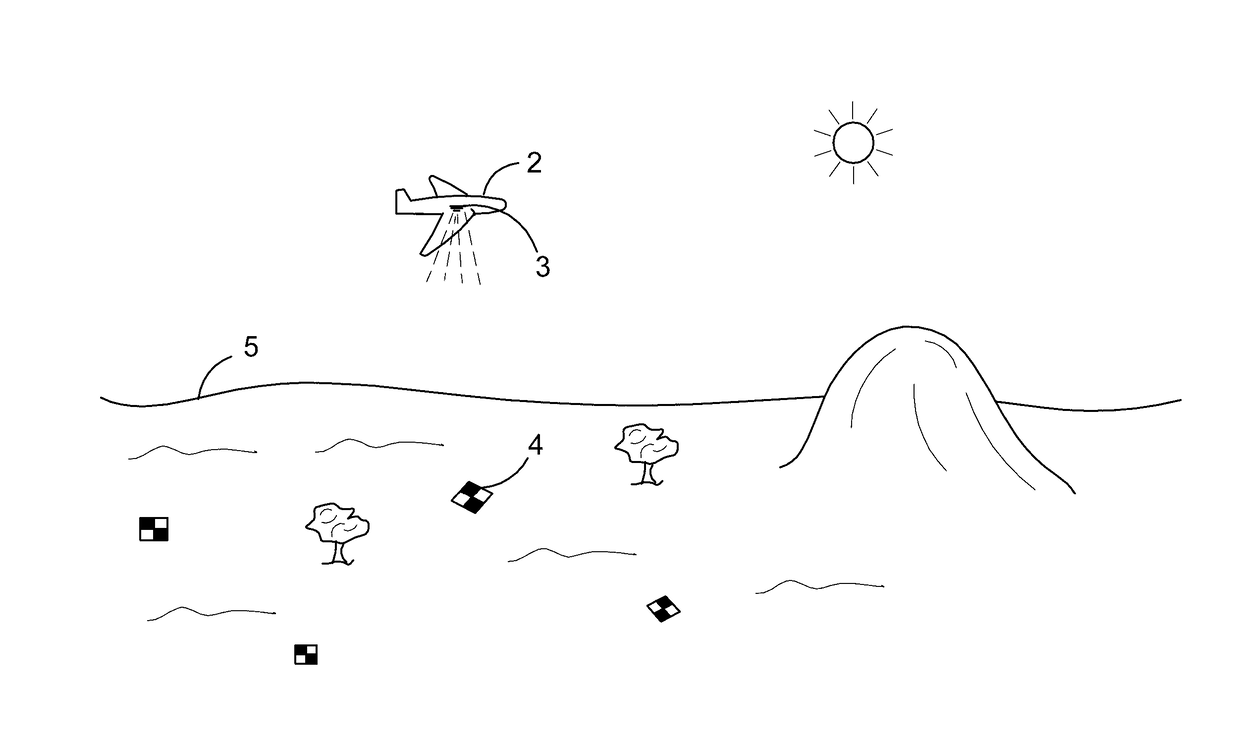
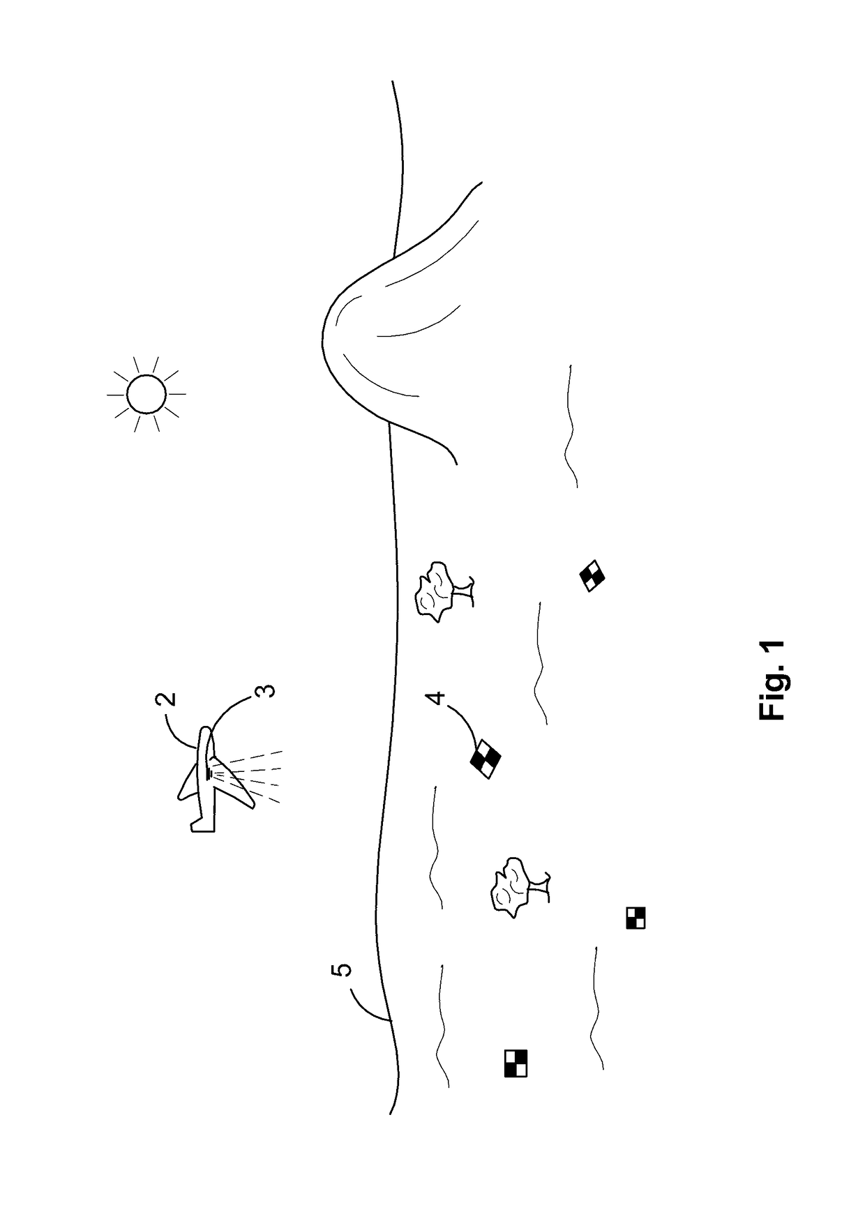
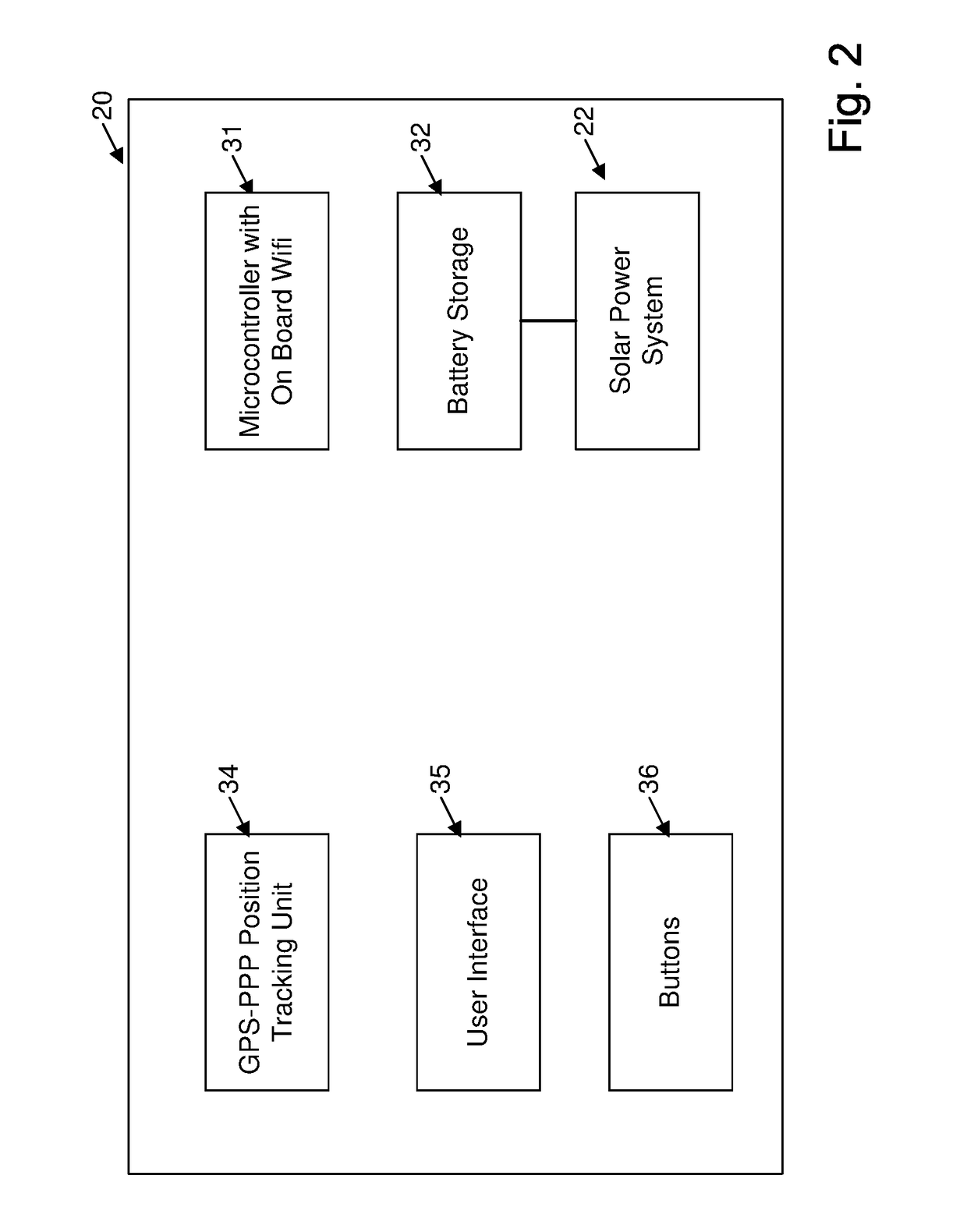
[0045]The preferred embodiment provides a low cost, easy to use positioning devices to provide highly accurate and largely automated georeferencing for aerial surveying. Most significantly, consumer grade, single frequency GPS receivers and antennas can be used to provide data accuracies comparable to geodetic grade units. Until now, unlocking the positioning precision in this low cost equipment meant individuals were required to both purchase an expensive RTK subscription and understand the logic and theory behind the post processing software RTKLIB. The preferred embodiments provide a simplified system of the user placing a rugged target unit out in the sun for two hours then turning on their phone hotspot. The user needs to know nothing about the underlying technology and is now able to produce survey grade datasets, without the effort or expense of sub-contracting traditional surveyors to capture GCPs.

[0046]UAV Surveying:

[0047]UAV surveying is typically conducted on sites rangin...


PUM


Abstract

Integrated Visual Geo-referencing Target Unit ABSTRACT A georeferencing target unit including: a generally planar top surface including a visual marker structure on the top surface, dimensioned to be observable at a distance by a remote visual capture device; an internal gps tracking unit tracking the current position of the target unit; a microcontroller and storage means for storing gps tracking data; and wireless network interconnection unit for interconnecting wirelessly with an external network for the downloading of stored gps tracking data; a power supply for driving the gps tracking unit, microcontroller, storage and wireless network interconnection unit, a user interface including an activation mechanism for activating the internal gps tracking unit to track the current position of the target unit over an extended time frame and store the tracked gps tracking data in the storage means.

Description

FIELD OF THE INVENTION[0001]The present invention is directed to providing a highly accurate, easy to use, automated georeferencing system and method for aerial surveying.BACKGROUND OF THE INVENTION[0002]Any discussion of the background art throughout the specification should in no way be considered as an admission that such art is widely known or forms part of common general knowledge in the field.[0003]There has been a recent dramatic increase in the ability to collect aerial survey data from satellites, planes and, more recently, inexpensive drones (UAV). The challenge that exists is both turning raw imagery from aerial capture by, for example, a UAV, into valuable surveying and inspection outputs, and also in visualizing and using the information without needing to be technically trained in expensive geospatial or computer aided design software.[0004]The ease of imagery capture has resulted in gigabytes of un-georeferenced imagery being uploaded by users. Unfortunately, in order...

Claims


Application Information

Patent Timeline
Patent Type & Authority Applications(United States)
IPC IPC(8): G01S19/45G01C21/00G01C21/04
CPCG01S19/45G01C21/005G01C21/04G01C11/00G01C11/025G01S19/42G01S19/421
Inventor SAN MIGUEL, RORY LEONGREER, FREDERICK JAMES
Owner PROPELLER AEROBOTICS PTY LTD
Why Eureka
Try Eureka