Image forming apparatus

a technology of forming apparatus and developing roller, which is applied in the direction of electrographic process, instruments, gearing, etc., can solve the problems of unstable inability to make a substantial right angle in the position of the developing roller zb>6/b>, and uneven contact pressure between the developing roller and the developing roller. achieve the effect of high accuracy and stable contact pressur

Active Publication Date: 2018-08-23
CANON KK
View PDF1 Cites 5 Cited by
  • Summary
  • Abstract
  • Description
  • Claims
  • Application Information

AI Technical Summary

Benefits of technology

[0007]An object of the present invention is to provide an image forming apparatus capable of positioning a developer carrying member with high accuracy with a stable contact pressure relative to an image bearing member.

Problems solved by technology

Here, when the developing cartridge is swingably supported relative to the photosensitive drum by the swing shaft, the alignment between a swing axis of the developing cartridge and a rotational axis of the developing roller may be deviated due to part tolerance or the like, with the result that the contact pressure between the developing roller and the developing roller may be uneven.
Hei 9-230694, there is a degree of freedom on the other end side of the developing roller, that is, it is not positively positioned there, and therefore, the position of the developing roller abutting on the surface of the photosensitive drum varies, with the result that the contact pressure of the developing roller with the photosensitive drum may be unstable in some cases.
However, from the standpoint of miniaturizing the process cartridge, it is necessary to increase the degree of freedom in the disposition direction of the swinging center of the developing cartridge with respect to the disposition of the image bearing member and the developer carrier, and therefore, the angle θZ2 at which the position of the developing roller Z6 is stabilized cannot be made substantially right angle in some cases.

Method used


Image

  • Image forming apparatus
  • Image forming apparatus
  • Image forming apparatus

Examples


first embodiment

(Image Forming Apparatus)

(1) Overall Structure

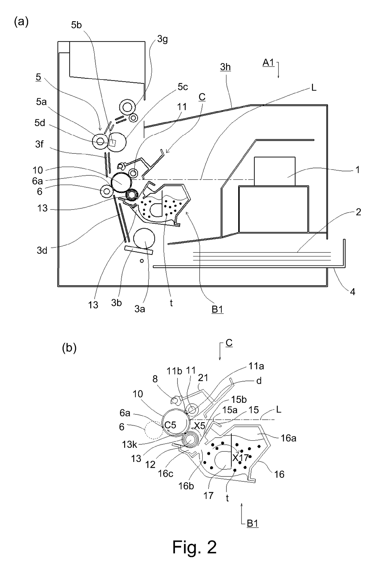
[0040]Part (a) of FIG. 2 shows a laser beam printer using an electrophotographic process as an image forming apparatus according to an embodiment of the present invention. Tins laser beam printer comprises a laser beam printer main assembly as an image forming apparatus main assembly, a drum cartridge dismountably mounted to the laser beam printer main assembly, and a developing cartridge. The main assembly of the image forming apparatus thereinafter referred to as the apparatus main assembly) is the remaining part of the image forming apparatus excluding the cartridge.

[0041]In the following description, the longitudinal direction of the drum cartridge and the developing cartridge is a direction substantially parallel to the rotation axis L1 of the photosensitive drum and the rotation axis L0 of the developing roller. Further, the rotation axis L1 of the photosensitive drum and the rotation axis L0 of the developing roller intersect (sub...

modification 1

(Modification 1)

[0273]In the above-described embodiment, the contact developing method in which the developing roller is contacted with the photosensitive drum at the time of image formation has been described. However, the present invention is not limited thereto, and is applicable to the non-contact type development, in which the developing roller is close to the photosensitive drum of the time of image formation.

modification 2

(Modification 2)

[0274]In the above-described embodiment, the structure of the cartridge B is a developing cartridge including the developing roller 13, but it is not limited thereto. A process cartridge in which a drum unit for supporting the photosensitive drum 10 and a developing unit 50 for supporting the developing roller 13 are integrated into a cartridge and is dismountable from the apparatus main assembly A may be used.

[0275]In the above-described embodiment, as the drum cartridge C, the photosensitive drum 10 is structured to be mountable to and dismountable from the apparatus main assembly A, but it is not limited thereto. For example, the photosensitive drum 10 (including the cleaning blade 20 and the charging roller 11) may be installed in the apparatus main assembly A.


PUM


Abstract

An image forming apparatus including a rotatable image bearing drum; a cartridge mountable to a main assembly and including a rotatable developer carrying sleeve; first and second bearings provided in the cartridge, supporting the sleeve at one axial and the other ends end of the sleeve, and having first and second regulated portions, respectively; third and fourth bearings, supporting the drum at one and the other axial ends of the drum, and having first and second regulating portions, respectively; first and second swingable members provided in the main assembly and fixed with one and the other ends and swingable integrally with the cartridge between a first position in which the sleeve contacts the drum and a second position in which the sleeve is spaced from the drum. When the cartridge is in the first position, the first and second regulated portions contact the first and second regulating portions respectively.

Description

FIELD OF THE INVENTION AND RELATED ART[0001]The present invention relates to an image forming apparatus, and is applicable to a laser beam printer, a facsimile apparatus, a word processor, and the like, for example, using an electrophotographic process.[0002]Conventionally, as a type of electrophotographic developing method, a contact developing method is known in which an image is formed with an elastic layer of a developing roller contacted with a surface of a photosensitive drum. In this case, it is necessary for the developing roller to contact the photosensitive drum uniformly in the axial direction of the photosensitive drum. To this end, there is a method in which a developer cartridge including a developing roller is rotatably supported relative to a photosensitive drum with a swing shaft thereof, arid a biasing member for exerting a moment in a direction in which the developing roller contacts the photosensitive drum, so that the developing cartridge is swingable relative t...

Claims


Application Information

Patent Timeline
Patent Type & Authority Applications(United States)
IPC IPC(8): G03G15/04F16C17/04
CPCG03G21/1857G03G21/1647G03G21/1842F16C17/04G03G2221/1861F16H21/44G03G21/1825G03G21/1853
Inventor KUDO, MASANORIKIMURA, TAKASHIMUNETSUGU, HIROYUKI
Owner CANON KK
Why Eureka
Try Eureka