Ground roller assembly

a technology of ground rollers and assembly parts, applied in the direction of apparatuses for overhead lines/cables, connection contact member materials, electrostatic charges, etc., can solve the problems of induction of electricity in the new conductor, induction of electrical charges that can be quite dangerous, and sometimes deadly, to the workers that are performing the installation, and the pivoting support arm

Inactive Publication Date: 2018-08-23
MACLEAN POWER LLC
View PDF8 Cites 5 Cited by
  • Summary
  • Abstract
  • Description
  • Claims
  • Application Information

AI Technical Summary

Benefits of technology

[0004]In one aspect, the present disclosure provides a ground roller assembly for grounding electrical current induced in a conductor during installation of high power transmission lines. The ground roller assembly may include a mounting bracket having a plurality of pivot points spaced away from a mounting aperture, and an integrally formed tongue projecting outwardly away from an upper edge of the mounting bracket. A support arm may be coupled to one of the plurality of pivot points positioned proximate to a side edge of the mounting bracket. A sheave configured to receive an electrical conductor may be attached to an end of the support arm opposite the mounting bracket.

Problems solved by technology

In other situations, the proximity to other live power lines or lightening can cause the induction of electricity in the new conductors during the installation process.
These inducted electrical charges can be quite dangerous, and sometimes deadly, to the workers that are performing the installation.
One disadvantage of currently-known ground roller assembly hardware is that a pivoting support arm that provides grounding for the pulled conductor mounts to the same location that the ground roller assembly mounts to the stringing block.
Thus, as force is placed on the pivoting support arm, it can cause the mounting hardware to loosen and may limit the ground roller assemblies' effectiveness.
Another disadvantage of the currently-known hardware is the size and amount of hardware need to mount the ground roller assembly to a stringing block.
This results in high production costs, and increased points of potential failure.

Method used


Image

  • Ground roller assembly
  • Ground roller assembly
  • Ground roller assembly

Examples


Embodiment Construction

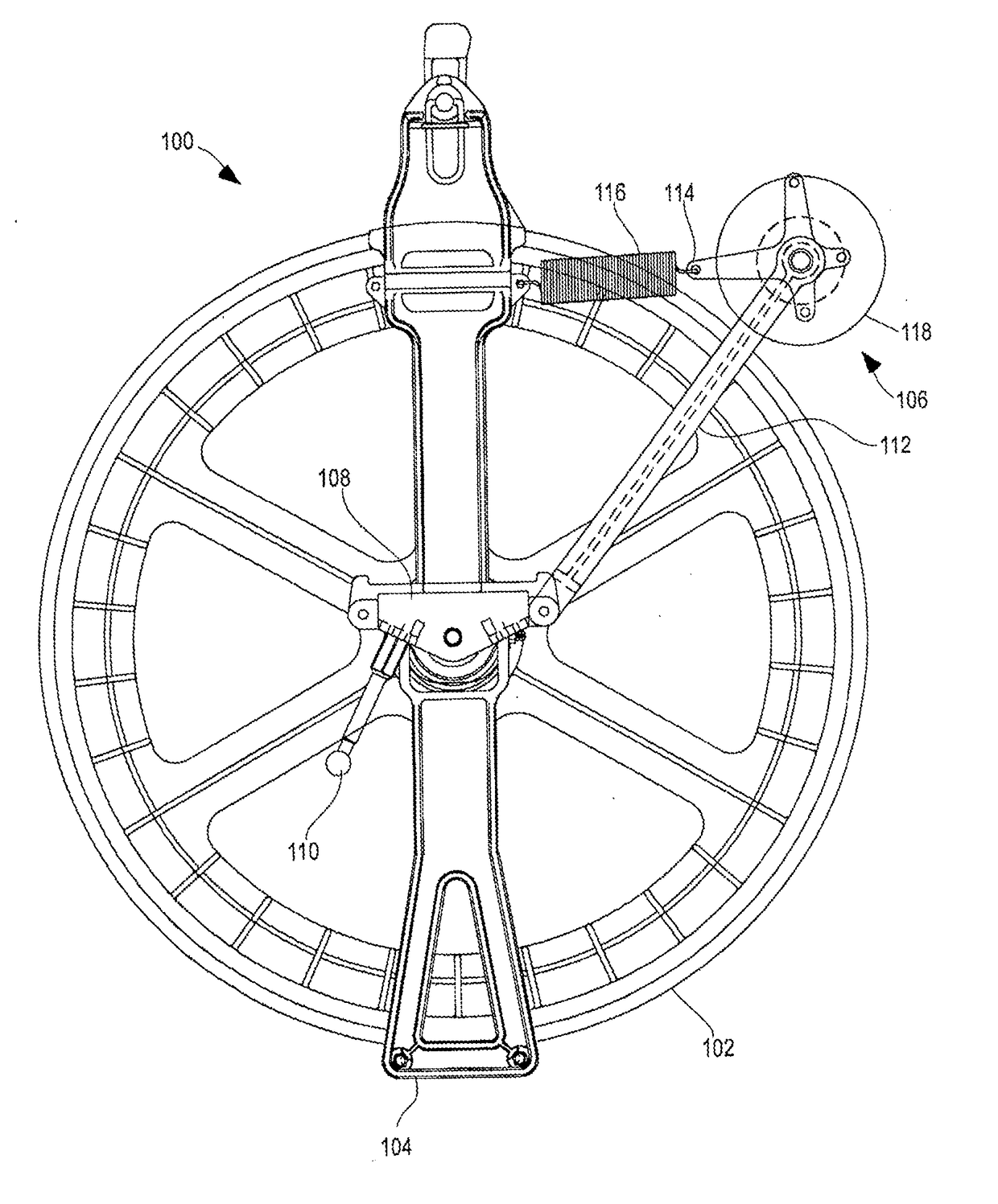
[0015]FIG. 1 shows a front view of a grounding system 100. The grounding system 100 includes a traditional stringing block 102 and stringing block frame 104, and an improved ground roller assembly that is generally depicted as 106. The ground roller assembly 106 attaches to a single side of stringing block frame 104 by a ground roller assembly mounting bracket 108 through use of a fastener, such as a bolt or other mounting pin. A tongue (see FIGS. 3-4, 6-8) formed in the side of the ground roller assembly mounting bracket 108 may mate with a channel in the stringing block frame 104 to stabilize and substantially prevent rotation of the ground roller assembly mounting bracket 108 when a conductor applies a force to the ground roller assembly 106. A grounding pin 110 may be mounted to the ground roller assembly mounting bracket 108 which may be connected to a grounding wire (not shown) for grounding any electrical charge that may build up in the grounding system 100.

[0016]Pivotally mo...


PUM


Abstract

The present disclosure provides a ground roller assembly for grounding electrical current induced in a conductor during installation of high power transmission lines. The ground roller assembly may include a mounting bracket having a plurality of pivot points spaced away from a mounting aperture, and an integrally formed tongue projecting outwardly away from an upper edge of the mounting bracket. A support arm may be coupled to one of the plurality of pivot points positioned proximate to a side edge of the mounting bracket. A sheave configured to receive an electrical conductor may be attached to an end of the support arm opposite the mounting bracket

Description

CROSS-REFERENCE TO RELATED APPLICATION[0001]The present patent document claims the benefit of the filing date under 35 U.S.C. § 119(e) of Provisional U.S. Patent Application Ser. No. 62 / 460,443, filed Feb. 17, 2017, which is hereby incorporated by reference.BACKGROUND[0002]During the installation process of high voltage transmission power lines, single or multiple conductors are strung between transmission towers. Stringing blocks may be suspended in the air from the transmission tower with the conductors running through the stringing block to aid in the installation process. In some instances, as the conductor is pulled through the stringing block static electricity is induced in the conductor because of the friction of the conductor against the stringing block. In other situations, the proximity to other live power lines or lightening can cause the induction of electricity in the new conductors during the installation process. These inducted electrical charges can be quite dangero...

Claims


Application Information

Patent Timeline
Patent Type & Authority Applications(United States)
IPC IPC(8): H05F3/02H02G1/04H01R4/64
CPCH05F3/02H02G1/04H01R4/646
Inventor LIN, WEI-CHUNGGOLDSMITH, MAXWELL
Owner MACLEAN POWER LLC
Why Eureka
Try Eureka