Vehicle body frame structure for saddle riding vehicle

Active Publication Date: 2018-08-30
HONDA MOTOR CO LTD
View PDF12 Cites 3 Cited by
  • Summary
  • Abstract
  • Description
  • Claims
  • Application Information

AI Technical Summary

Benefits of technology

The patent text describes a problem in a vehicle body frame structure, where the ratio of the thickness of the sidewall to the thickness of the upper and lower walls of the main frame cannot be lowered to a certain degree or more during casting, which can result in blowhouses or misrun of melted metal. The technical effect of the patent is to solve this problem by providing a new design for the vehicle body frame structure that allows for a lower ratio of the sidewall to the upper and lower walls without compromising the quality of the casting process.

Problems solved by technology

However, in the vehicle body frame structure disclosed in Japanese Unexamined Patent Application, First Publication No. 2007-62618, since the main frame is formed of a metal material as a whole, in order to avoid occurrence of a blowhole or misrun of melted metal during casting, a ratio of a thickness of a sidewall with respect to a thickness of upper and lower walls of the main frame cannot be lowered to a certain degree or more.
That is, when the ratio of the thickness of the sidewall with respect to the thickness of the upper and lower walls of the main frame is lowered to the certain degree or more, during casting, a blowhole easily occurs in the upper and lower walls, and the misrun of melted metal easily occurs in the sidewall.
For this reason, in the vehicle body frame structure disclosed in Japanese Unexamined Patent Application, First Publication No. 2007-62618, because it is difficult due to manufacturing limitations to simultaneously provide adequate deflection characteristics in the leftward / rightward direction of the main frame and high rigidity in the upward / downward direction, an advanced manufacturing technology is required, and cost is high.

Method used


Image

  • Vehicle body frame structure for saddle riding vehicle
  • Vehicle body frame structure for saddle riding vehicle
  • Vehicle body frame structure for saddle riding vehicle

Examples


first embodiment

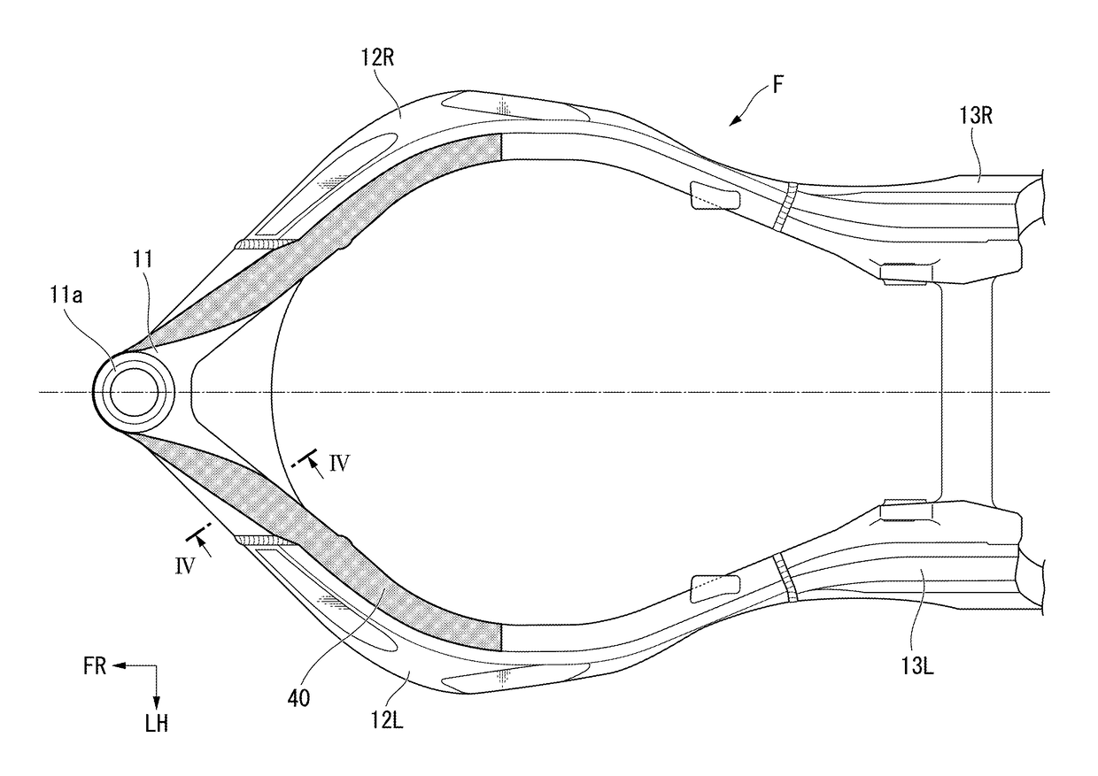
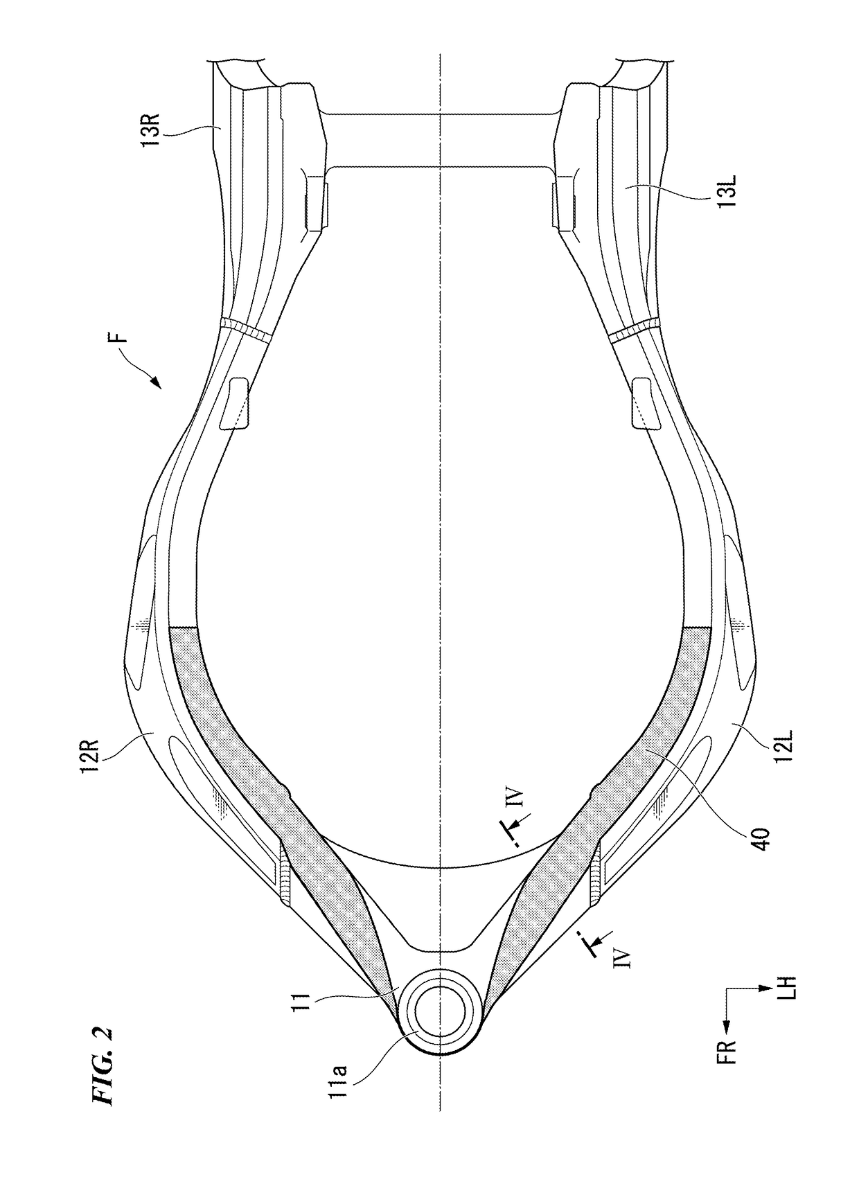
[0019]FIG. 2 is a plan view of a vehicle body frame of the present invention.

[0020]FIG. 3 is a side view of the vehicle body frame of the first embodiment of the present invention.

[0021]FIG. 4 is a cross-sectional view taken along line IV-IV in FIG. 2 of the vehicle body frame of the first embodiment of the present invention.

second embodiment

[0022]FIG. 5 is a side view of a vehicle body frame of the present invention.

[0023]FIG. 6 is a perspective view of the vehicle body frame of the second embodiment of the present invention.

[0024]FIG. 7 is a cross-sectional view taken along line VII-VII in FIG. 6 of the vehicle body frame of the second embodiment of the present invention.


PUM


Abstract

A vehicle body frame includes a head section that rotatably supports a steering shaft, and main frames extending from the head section toward a rear side of a vehicle body. A cross section of the main frame in a direction crossing a vehicle body forward / rearward direction is formed in a substantially rectangular shape having a vertical width larger than a lateral width. A carbon fiber reinforced resin in which carbon fibers are oriented uniformly in the vehicle body forward / rearward direction is installed on at least one of upper surfaces and lower surfaces of the main frames.

Description

CROSS-REFERENCE TO RELATED APPLICATION[0001]Priority is claimed on Japanese Patent Application No. 2017-036350, filed Feb. 28, 2017, the content of which is incorporated herein by reference.BACKGROUNDField of the Invention[0002]The present invention relates to a vehicle body frame structure for a saddle riding vehicle.Description of Related Art[0003]There is known a vehicle body frame for a saddle riding vehicle such as a motorcycle or the like including a head section configured to pivotably support a steering shaft, and a pair of left and right main frames extending from the head section toward a rear side of a vehicle body, wherein a pivot frame configured to vertically swingably support a swing arm is connected to rear sections of the pair of left and right main frames, and a power unit is supported by the main frames and the pivot frame (for example, see Japanese Unexamined Patent Application, First Publication No. 2007-2618).[0004]In the vehicle body frame structure disclosed ...

Claims


Application Information

Patent Timeline
IPC IPC(8): B62K11/04B62K19/12B62H1/02B62K25/28
CPCB62K11/04B62K19/12B62H1/02B62K25/28
Inventor IWAKAMI, HIROSHISHIKANAI, SHIMPEI
Owner HONDA MOTOR CO LTD
Why Eureka
Try Eureka