Floating water mat reel

a reel and water mat technology, applied in the field of reels for floating water mats, can solve the problems of difficult removal of mats and difficult rolling of mats for storage, and achieve the effect of convenient connection, quick assembly and disassembly

Active Publication Date: 2018-09-06
BEHRENDT DAVID DONALD
View PDF18 Cites 6 Cited by
  • Summary
  • Abstract
  • Description
  • Claims
  • Application Information

AI Technical Summary

Benefits of technology

[0007]A floating water mat reel includes a plurality of plates connected to an axle. A floating water mat is selectively connected to the plates. Preferably, the plates have a slot that receives and frictional

Problems solved by technology

When individuals are finished using the mats, because of their size, as well as their position relative to a dock o

Method used


Image

  • Floating water mat reel
  • Floating water mat reel
  • Floating water mat reel

Examples


Embodiment Construction

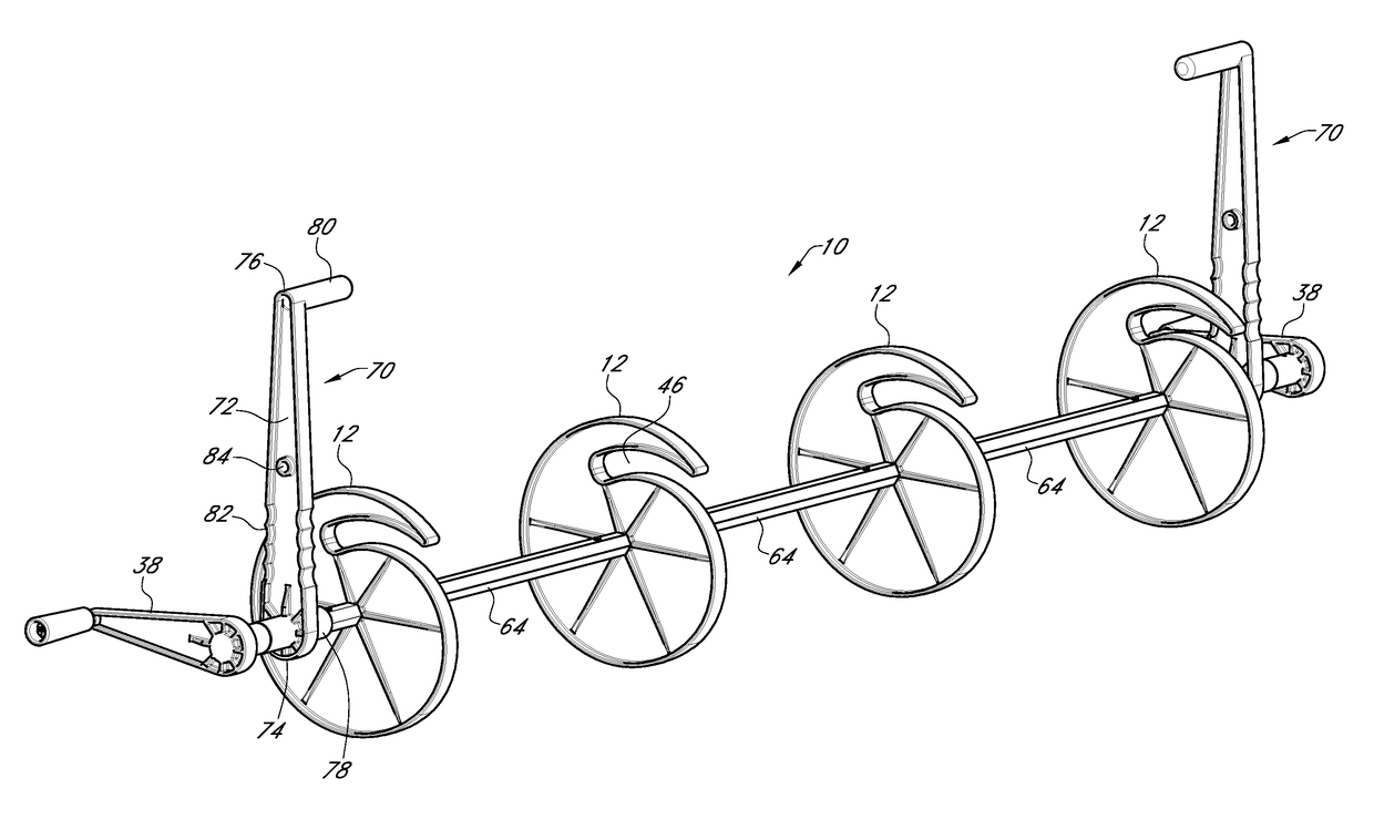
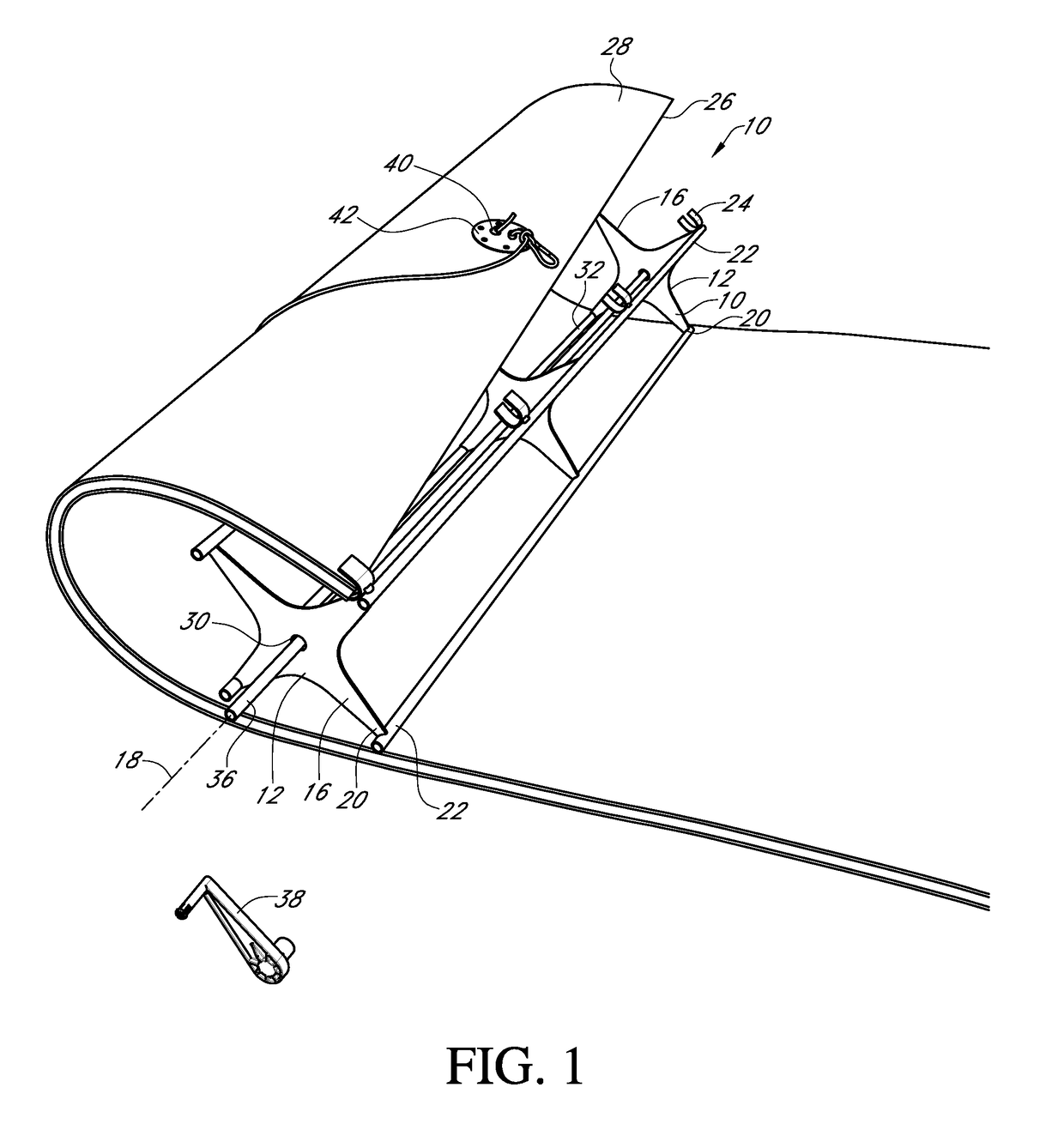
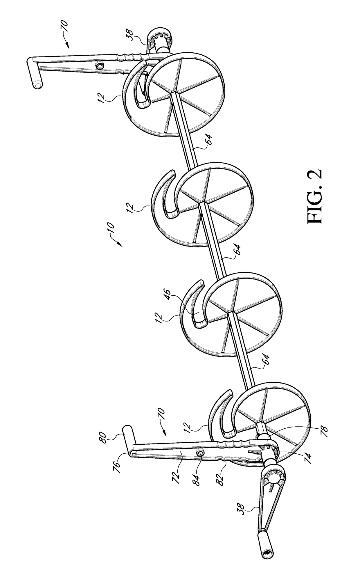
[0013]Referring to the Figures, a floating water mat reel 10 includes a pair of end plates 12 and a center plate 14 positioned between the end plates 12. The plates 12 and 14 are of any size, shape and structure. In a preferred embodiment the plates 12 and 14 have a plurality of fingers 16 that extend radially outward from a central axis 18 of the plates 12 and 14. The fingers 16 of plates 12 and 14 are horizontally aligned.

[0014]Connected to the outer end or tip 20 of the fingers are a plurality of support rods 22. The support rods 22 extend from one end plate 12 to the other end plate 12. Connected to at least one of the support rods 22 are a plurality of receiving members 24 that are formed and positioned to receive one end 26 of a floating mat 28.

[0015]Extending through central openings 30 in plates 12 and 14 and connected to plates 12 and 14 is an axle 32. In a preferred embodiment, the axle 32 has a central elongated member 34 and a pair of outer members 36 that are slidably a...


PUM


Abstract

A floating water mat reel that has a plurality of plates mounted to an axle. A floating water mat is selectively connected to the plates. A crank, connected to the axle is used to rotate the plates so that the mat wraps around the plate.

Description

CROSS REFERENCE TO RELATED APPLICATION[0001]This application claims the benefit to Provisional Application U.S. Ser. No. 62 / 466,577 filed on Mar. 3, 2017.BACKGROUND OF THE INVENTION[0002]This invention is directed to a reel for a floating water mat, and more particularly to a floating water mat reel for a boat.[0003]Floating water mats are well known in the art for recreational and entertainment uses. Typically, floating water mats are attached to a dock or boat when in use. When individuals are finished using the mats, because of their size, as well as their position relative to a dock or boat, the mats are challenging to remove. In addition, once removed, the mats are challenging to roll for storage. Therefore, a device is needed that addresses these deficiencies.[0004]An objective of the present invention is to provide a reel that makes rolling up a mat easier.[0005]Another objective of the present invention is to provide a reel that is easy to assemble and take apart.[0006]These...

Claims


Application Information

Patent Timeline
IPC IPC(8): B65H75/22B65H75/28B65H18/02B65H18/10
CPCB65H75/22B65H75/285B65H18/028B65H18/10B63B35/73B65H75/18B65H75/28B65H75/30B65H2701/1133B63B34/50B65H75/241B65H75/2254B65H75/2218B65H2301/41427B65H2701/1922
Inventor BEHRENDT, DAVID DONALD
Owner BEHRENDT DAVID DONALD
Why Eureka
Try Eureka