Assembly Comprising a Support Bracket, Which Diverts Reaction Torques, and a Power Screwdriver

Active Publication Date: 2018-09-13
HOHMANN JORG +1
View PDF5 Cites 0 Cited by
  • Summary
  • Abstract
  • Description
  • Claims
  • Application Information

AI Technical Summary

Benefits of technology

The invention relates to a fixing apparatus for power screwdrivers, which uses a groove on the gear housing to securely lock the support bracket. Compared to existing solutions, the invention has low wear and is easy to use. The fixing apparatus includes an actuating element, a locking element, and a compression spring. The actuating element is a pin that can be actuated from the side, making it more accessible. The locking element is a component part of the fixing apparatus and engages with the groove to securely lock it. The compression spring holds the pin in position and can be easily removed and replaced. The invention also allows for the removal of the plug for maintenance purposes and the sealing of further bores with plugs.

Problems solved by technology

Often the generated reaction torques are difficult to estimate beforehand and can lead to an incalculable risk for the user, and perhaps cause kickback of the power screwdriver.
A drawback in this context can be that fastening in the longitudinal direction is based solely on clamping or friction forces.
There is hence the danger that, when appropriate compressive or tensile load is exerted by the bracket on the power screwdriver, the fastening setting is released, and the support bracket, together with fastening flange, slips off from the gear housing of the power screwdriver.
Also, in such a fastening action based on clamping and friction forces, increased material wear through material abrasion occurs.

Method used


Image

  • Assembly Comprising a Support Bracket, Which Diverts Reaction Torques, and a Power Screwdriver
  • Assembly Comprising a Support Bracket, Which Diverts Reaction Torques, and a Power Screwdriver
  • Assembly Comprising a Support Bracket, Which Diverts Reaction Torques, and a Power Screwdriver

Examples


Embodiment Construction

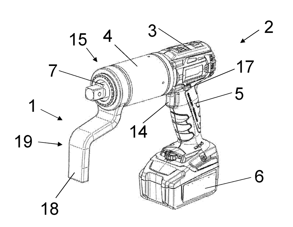
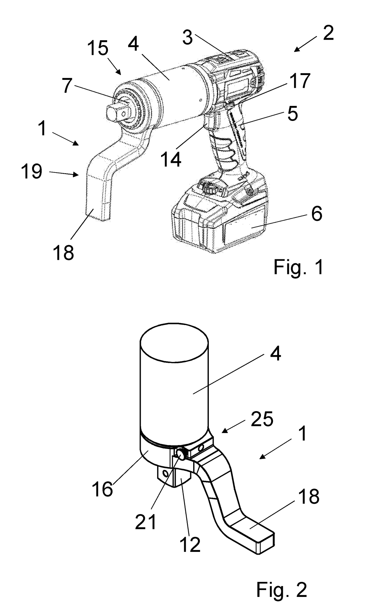
[0022]Component parts of the assembly according to the invention are a power screwdriver 2 and a support bracket 1 which absorbs screwdriving torques. FIG. 1 shows a corresponding power screwdriver 2 having a support bracket 1 fastened thereto. The power screwdriver 2 is comprised firstly of a drive part 3 and a gear housing 4. The two components can also be connected to each other, for example, via a swivel joint.

[0023]In the drive part 3, a motorized device can be provided for the operation of the power screwdriver 2. In principle, a pneumatic or electric operating method can also be considered. Moreover, close to the drive part 3, a handle 5 and a storage battery 6 or other battery can be provided. Such a storage battery (rechargeable battery) 6 can be exchangeably fastened to the power screwdriver 2. The storage battery 6 provides the required electrical energy for the operation of the power screwdriver 2. Naturally, such a power screwdriver 2 can also be supplied with electrica...


PUM


Abstract

A power screwdriver has a gear housing with forwardly extending output shaft and a peripheral external spline with teeth lying on a first diameter. The gear housing has a peripheral groove with groove bottom arranged rearward of the external spline. The groove bottom lies on a second diameter smaller than the first diameter. The support bracket has a fastening portion with an annular fastening flange with internal spline and a support foot arranged laterally offset from the output shaft and placed against an external counter bearing for diverting reaction torques. Internal and external splines cooperate to rotationally fix the support bracket relative to the gear housing. A locking element on the fastening flange can assume a blocking setting or a release setting. In the blocking setting, the locking element extends partially or completely into the groove and locks the support bracket to the gear housing in longitudinal direction.

Description

BACKGROUND OF THE INVENTION[0001]The invention relates to an assembly comprising a support bracket, which diverts reaction torques, and a power screwdriver, which has a drive part and a gear housing having an output shaft extending forwardly out of the gear housing. Around the gear housing, an external spline is provided, the teeth of which extend rearward up to a groove surrounding the gear housing over the periphery thereof. The groove bottom of the groove lies on a diameter which is smaller than the diameter of the circle described by the tips of the teeth. The support bracket has a fastening portion having an annular fastening flange and an internal spline, and further has a support foot, which is arranged laterally offset from the output shaft and is placeable against an external counter bearing. The spline of the fastening flange cooperates with the spline of the gear housing such that the support bracket is rotationally fixed relative to the gear housing. On the fastening fla...

Claims


Application Information

Patent Timeline
IPC IPC(8): B25B23/00B25B21/00B25F5/02B25F5/00
CPCB25B23/0078B25B21/00B25F5/025B25F5/001F16H57/02F16H2057/02026B25B27/14B25F5/02
Inventor HOHMANN, JORGHOHMANN, FRANK
Owner HOHMANN JORG
Why Eureka
Try Eureka