Hybrid fitting with water jet detection

Active Publication Date: 2017-12-28
GROHE
View PDF4 Cites 0 Cited by
  • Summary
  • Abstract
  • Description
  • Claims
  • Application Information

AI Technical Summary

Benefits of technology

The present invention is a sanitary fitting that is economical to produce, allows a use of standard components, and has low wear. The invention uses the sensor already present in a hybrid fitting to obtain information as to whether a manual regulation of the hybrid fitting was performed by means of an adjusting lever or whether a sensor-controlled regulation of a predefined water jet should take place. Consequently, more economical manufacture is made possible of a hybrid fitting that can be constructed with standard components and also has lower wear because of reduced additional mechanical measuring elements. The described mode of operation of the sanitary fitting also offers high operational reliability. It is now possible for even a minimal emerging water jet to be detected that known mechanical measuring elements would not yet be able to detect. The sensor arrangement includes at least one optical or acoustic sensor that is arranged in alignment with the water jet, and wherein the detection area has a detection area width that is greater than a diameter of a water jet. Even though it is dispensed with an additional mechanical sensor to detect a stroke of the actuator, the present invention achieves substantially lower wear of the sanitary fitting.

Problems solved by technology

Because of the additional measuring elements, prior art hybrid fittings are generally expensive, and it is not possible to use standard components, in particular standard single-lever mixers, adjusting levers, and / or standard valves.
Moreover, the additional mechanical measuring elements contribute to increased wear of the prior art hybrid fittings.

Method used


Image

  • Hybrid fitting with water jet detection
  • Hybrid fitting with water jet detection
  • Hybrid fitting with water jet detection

Examples


Embodiment Construction

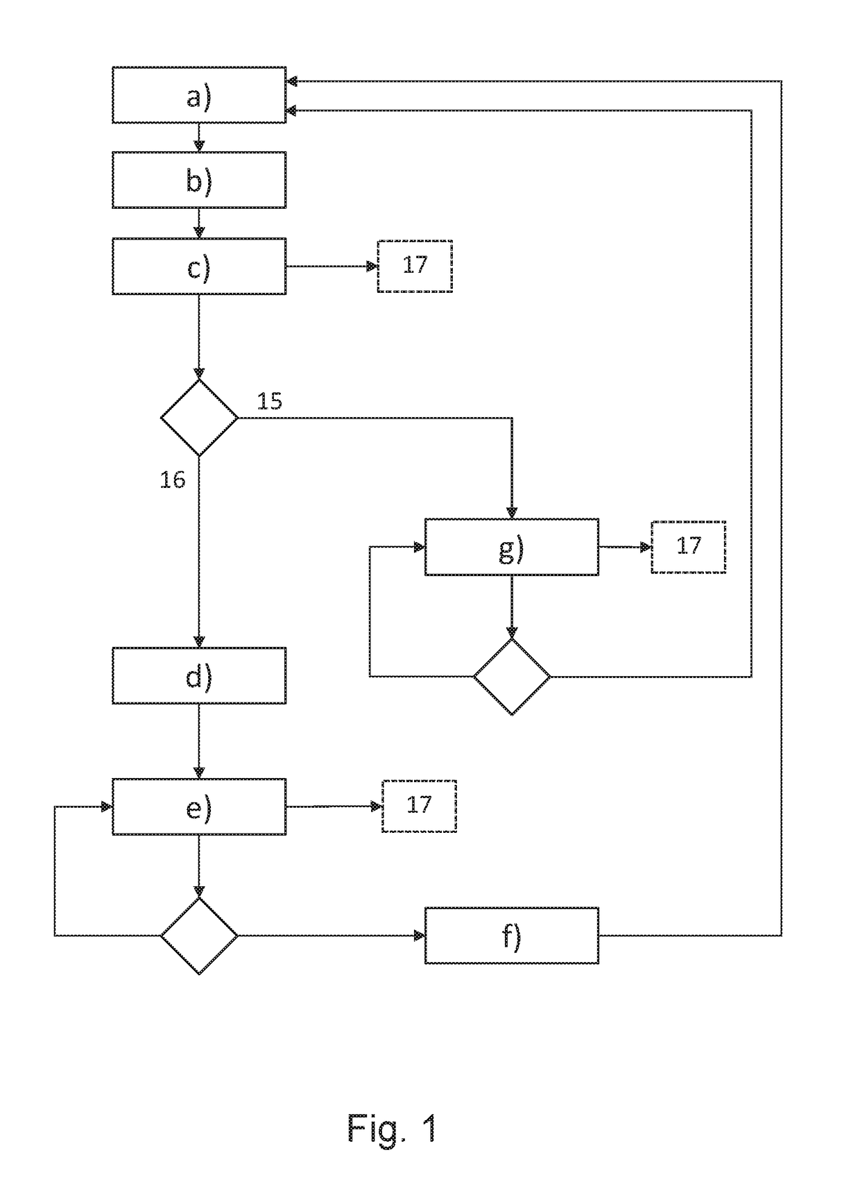
[0043]FIG. 1 shows a schematic and basic illustration of the method for operating a sanitary fitting. The method starts here in step a) with the monitoring by the sensor arrangement of an external detection area. If an object is present in the detection area, then detection by the sensor arrangement of the presence of an object in the detection area follows in step b). This is followed in step c) by an evaluation of the object detected first and a distinguishing of whether the first detected object is a water jet or a different object. The method can be carried out by means of a microcontroller by way of example. The microcontroller here also has a memory unit. State variables can be stored in the memory unit. In step c) an object state variable 17 is stored here. The object state variable 17 can assume three values or three states. The first state is referred to here as “water jet” and is stored when it has been determined in step c) that the first detected object is a water jet. T...


PUM


Abstract

A method for operating a sanitary fitting, and to a sanitary fitting. The sanitary fitting is equipped to deliver a water jet and has at least one manual actuator for manual regulation of at least one water jet flow rate or a water jet temperature, and a sensor arrangement that is equipped for sensor-controlled regulation of a predefined water jet flow rate and a predefined water jet temperature, wherein the sensor arrangement is equipped to detect the presence of an object in an external detection area and wherein a control unit is provided that is equipped to evaluate an object detected first and to distinguish whether the object detected first is a water jet or a different object. The present invention makes possible an economical production, the use of standard components, and low wear.

Description

[0001]This nonprovisional application is a continuation of International Application No. PCT / EP2016 / 000379, which was filed on Mar. 4, 2016, and which claims priority to German Patent Application No. 10 2015 002 779.4, which was filed in Germany on Mar. 6, 2015, and which are both herein incorporated by reference.BACKGROUND OF THE INVENTIONField of the Invention[0002]The present invention relates to a method for operating a sanitary fitting, and to a sanitary fitting having at least one manual actuator and a sensor arrangement. The sanitary fitting serves, in particular, to regulate a water jet flow rate and / or a water jet temperature.Description of the Background Art[0003]Sanitary fittings are, in particular, thermostatic mixing fittings that are designed as washbasin fittings, shower fittings, or bathtub fittings. To this end, the sanitary fittings frequently have a hot water inlet for hot water and a cold water inlet for cold water. In this case, the hot water and the cold water ...

Claims


Application Information

Patent Timeline
IPC IPC(8): B05B12/00B05B12/10B05B12/12E03C1/04B05B12/08F16K31/06G01V8/10
CPCB05B12/008B05B12/082B05B12/10G01V8/10E03C1/0408F16K31/0675B05B12/122E03C1/057E03C1/055
Inventor SCHOENBECK, HEIKOJUNG, ANDREASSTEINHOFF, STEFAN
Owner GROHE
Why Eureka
Try Eureka