Plug-in connection having a fixed line

Active Publication Date: 2014-10-16
ROBERT BOSCH GMBH
View PDF8 Cites 0 Cited by
  • Summary
  • Abstract
  • Description
  • Claims
  • Application Information

AI Technical Summary

Benefits of technology

The present invention provides a low-wear plug-in connection that increases vibration resistance and wear resistance. The direct mechanical contact between the conductor and the contact carrier prevents movement of the line or conductor on the contact element, reducing wear and tear between the parts. This line fixation increases the service life of the plug-in connection or allows it to handle higher vibration loads without wear and tear.

Problems solved by technology

During operation, a plug-in connection is subject to high vibration loads.
This may result in a relative movement between the pin and the contact, which in turn causes wear and consequently an increase of the contact resistance.
This may result in a premature failure of the plug-in connection.
This may furthermore result in a relative movement between the pin and the contact and thus in premature wear.

Method used


Image

  • Plug-in connection having a fixed line
  • Plug-in connection having a fixed line
  • Plug-in connection having a fixed line

Examples


Embodiment Construction

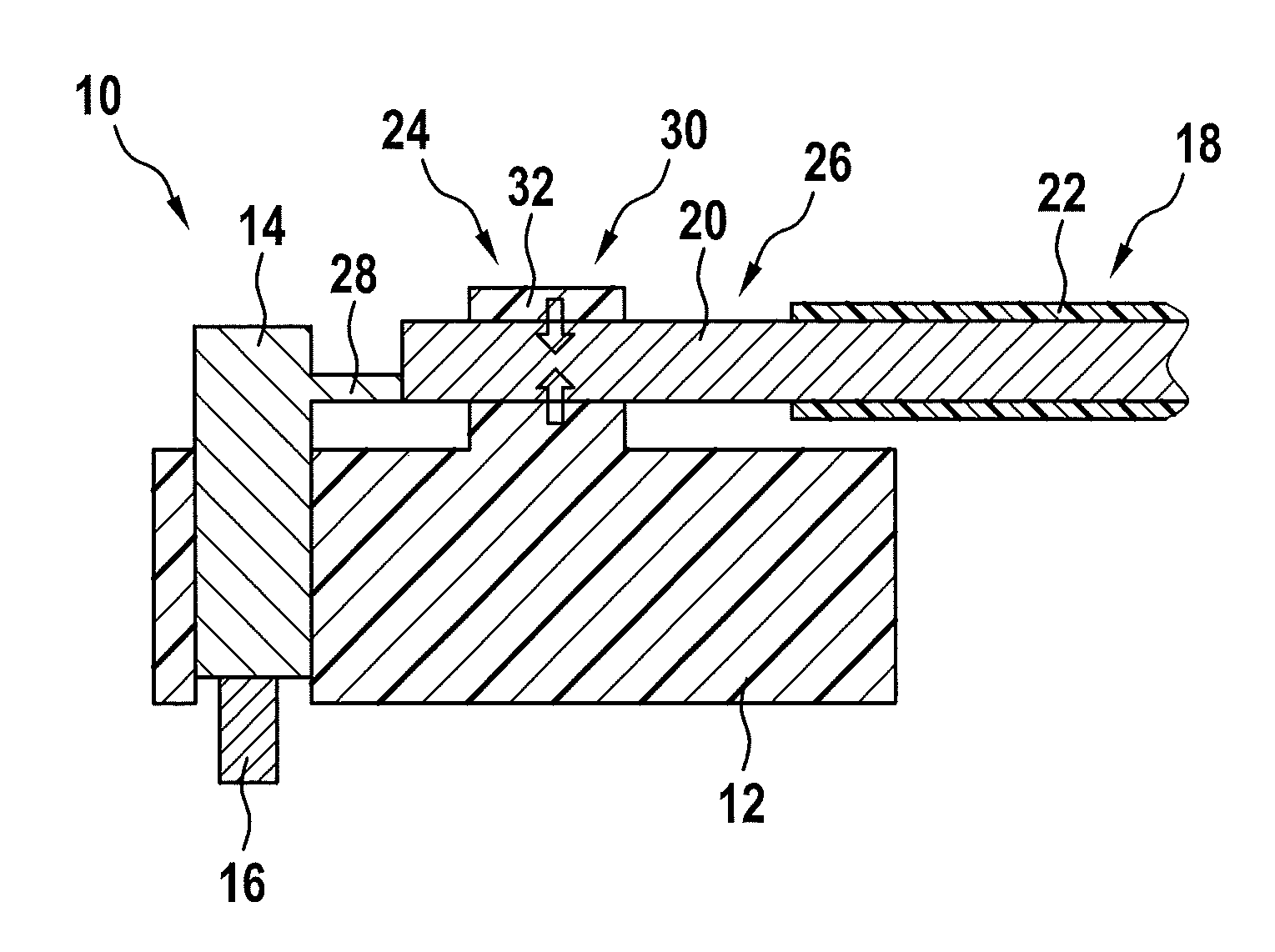
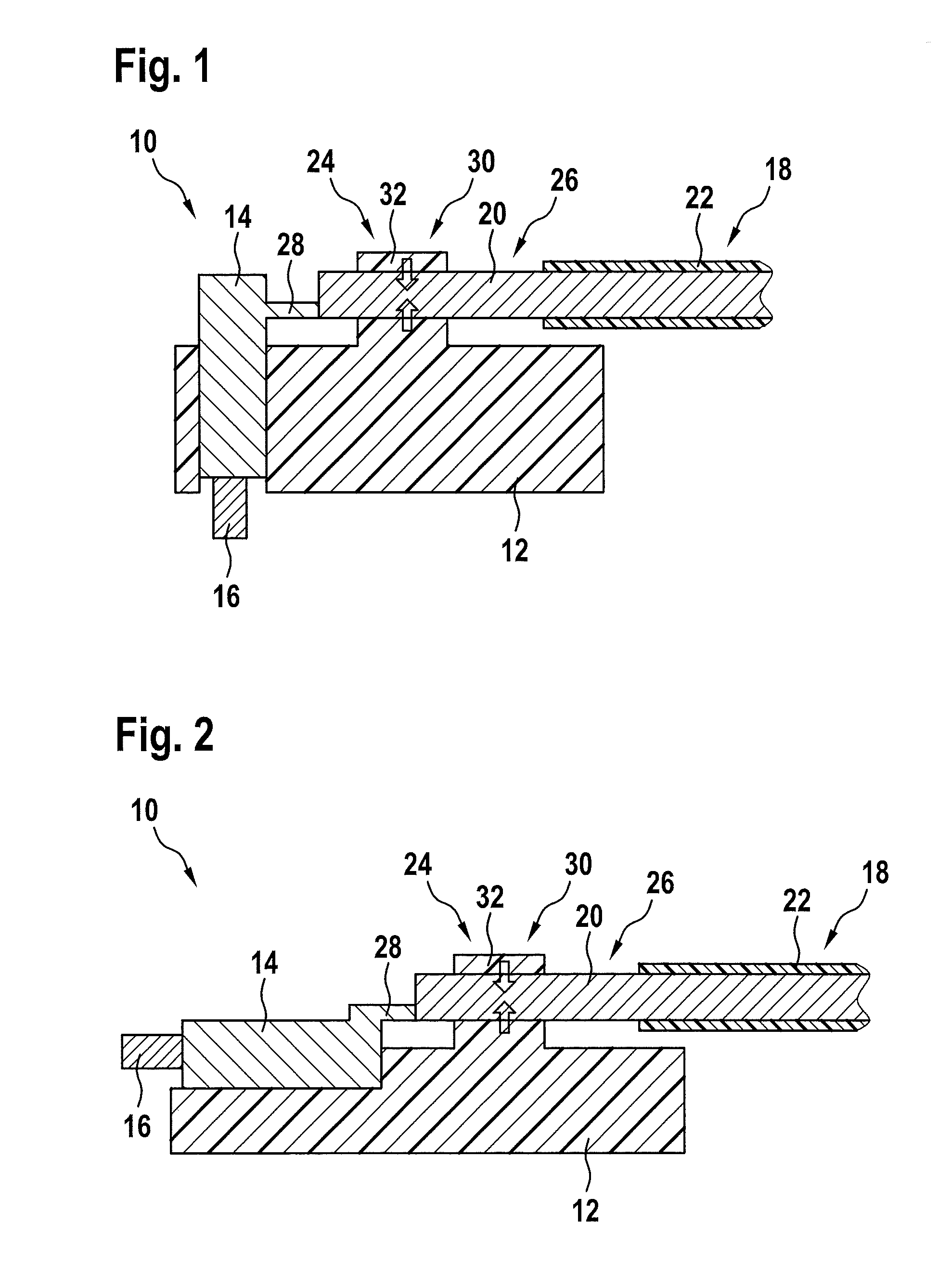
[0023]FIGS. 1 and 2 show a plug-in connection 10, which has a contact carrier 12 to which is attached a contact element 14 or a contact 14. The contact carrier may be made of a non-conductive material, such as a plastic.

[0024]Electrically conductive contact element 14 is designed to be pushed on a pin 16 and to accommodate it, in order to establish an electrical connection with pin 16. It should, however, be understood that the plug-in connection may have a pin instead of contact element 14, which may be plugged into a corresponding contact element.

[0025]Contact carrier 12 may, for example, be an integral part of a plug connector, which may be used to electrically and mechanically connect a cable harness to a power unit or a control unit of a vehicle. For example, pin 16 may be attached to a housing of the power unit or control unit.

[0026]Plug-in connection 10 of FIG. 1 has a cable outlet, which is rotated by 90° in relation to pin 16. Contact element 14 has a plug direction which r...


PUM


Abstract

A plug-in connection is described having a contact carrier including a contact element, which is mechanically connected to the contact carrier; a line has an electrical conductor, which is electrically connected to the contact element, and has an insulation which surrounds the electrical conductor. The line is mechanically connected to the contact carrier, the plug-in connection having a fixing element, into which is accommodated an uninsulated area of the line in which the electrical conductor is not surrounded by the insulation, and which fixes the electrical conductor to the contact carrier.

Description

FIELD OF THE INVENTION [0001]The present invention relates to a plug-in connection via which, for example, a cable harness may be connected to an electrical device.BACKGROUND INFORMATION[0002]A plug-in connection may include, for example, one or multiple electrical lines, the electrical conductors of which are each conductively connected to a contact element, for example, a pin socket, which may be attached to a corresponding, complementary contact element, for example, a pin.[0003]During operation, a plug-in connection is subject to high vibration loads. Due to this vibration load, the lines are moved and may transfer this movement to the directly connected contact. This may result in a relative movement between the pin and the contact, which in turn causes wear and consequently an increase of the contact resistance. This may result in a premature failure of the plug-in connection.[0004]A possible measure for reducing the wear-inducing line movement is to fix the line in / on or outs...

Claims


Application Information

Patent Timeline
IPC IPC(8): H01R13/627
CPCH01R13/627H01R4/38H01R13/5205H01R13/62
Inventor SAUR, MARTINLUX, MARKUS
Owner ROBERT BOSCH GMBH
Why Eureka
Try Eureka