Printing apparatus, printing system, printing control method and computer-readable recording medium

a printing control method and printing system technology, applied in printing, typewriters, etc., can solve the problems of increasing the manufacturing cost of the product, the inability to normally wind the ink ribbon, and the deterioration of printing quality

Active Publication Date: 2018-09-13
CASIO COMPUTER CO LTD
View PDF1 Cites 3 Cited by
  • Summary
  • Abstract
  • Description
  • Claims
  • Application Information

AI Technical Summary

Benefits of technology

[0011]According to another aspect of the present invention, a printing system includes a printing apparatus and a computer. The printing apparatus includes a thermal head which is configured to print an image by printing a plurality of lines on a medium, and a processor. The computer is provided separately from the printing apparatus. The thermal head includes a plurality of heat-generating elements configured to generate heat when a voltage is applied thereto in an application time, and the thermal head is controlled to sequentially print each of the plurality of lines on the medium. The computer is configured to: determine a specific line among the plurality of lines based on printing data for printing each of the plurality of lines, the specific line being a line estimated to have a possibility of sticking, and generate adjustment data for setting two or more lines among the plurality of lines, as the adjustment target lines, two or more lines being immediately before the specific line, and output the adjustment data to the printing apparatus. The processor is configured to: set the adjustment target lines based on the adjustment data, and adjust the application time of each of the adjustment target lines so that a difference between the application time and a reference application time is larger as each line is closer to the specific line, the reference application time being set based on a temperature of the thermal head.
[0012]According to another aspect of the present invention, a printing control method is a method of a printing apparatus. The printing apparatus includes a thermal head which is configured to print an image by printing a plurality of lines on a medium. The thermal head includes a plurality of heat-generating elements configured to generate heat when a voltage is applied thereto in an application time, and the thermal head is controlled to sequentially print on each of the plurality of lines on the medium. The printing control method comprises: determining a specific line among the plurality of lines based on printing data for printing the plurality of lines, the specific line being a line estimated to have a possibility of sticking; and adjusting the application time of an adjustment target line so as to be shorter than a reference application time, the adjustment target line being at least one line among the plurality of lines, the at least one line being a line which is to be printed immediately before the specific line, the reference application time being set based on a temperature of the thermal head.
[0013]According to another aspect of the present invention, a computer-readable recording medium having a printing control program controls a printing apparatus recorded therein. The printing apparatus includes a thermal head which is configured to print an image by printing a plurality of lines on a medium. The thermal head includes a plurality of heat-generating elements configured to generate heat when a voltage is applied thereto in an application time, and the thermal head is controlled to sequentially print each of the plurality of lines on the medium. The printing control program is configured to allow a computer: to determine a specific line among the plurality of lines based on printing data for printing the plurality of lines, the specific line being a line estimated to have a possibility of sticking; and to adjust application time of an adjustment target line so as to be shorter than a reference application time, the adjustment target line being at least one line among the plurality of lines, the at least one line being a line which is to be printed immediately before the specific line, the reference application time being set based on a temperature of the thermal head.

Problems solved by technology

When the sticking occurs, it is not possible to normally wind the ink ribbon.
Thereby, a region in which the printing is not normally performed is partially generated, so that a printing quality is remarkably deteriorated.
When a circuit for chopper control is added to the printing apparatus, the manufacturing cost of the product increases.
In the meantime, implementation of the chopper control by software makes a control program complicated and causes the size to increase.

Method used


Image

  • Printing apparatus, printing system, printing control method and computer-readable recording medium
  • Printing apparatus, printing system, printing control method and computer-readable recording medium
  • Printing apparatus, printing system, printing control method and computer-readable recording medium

Examples


Embodiment Construction

[0031]A printing apparatus in accordance with illustrative embodiments of the disclosure will be described in detail with reference to the drawings.

First Illustrative Embodiment

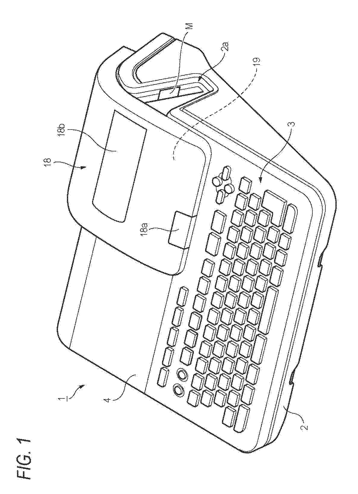
[0032]FIG. 1 is a perspective view of a printing apparatus 1 in accordance with a first illustrative embodiment.

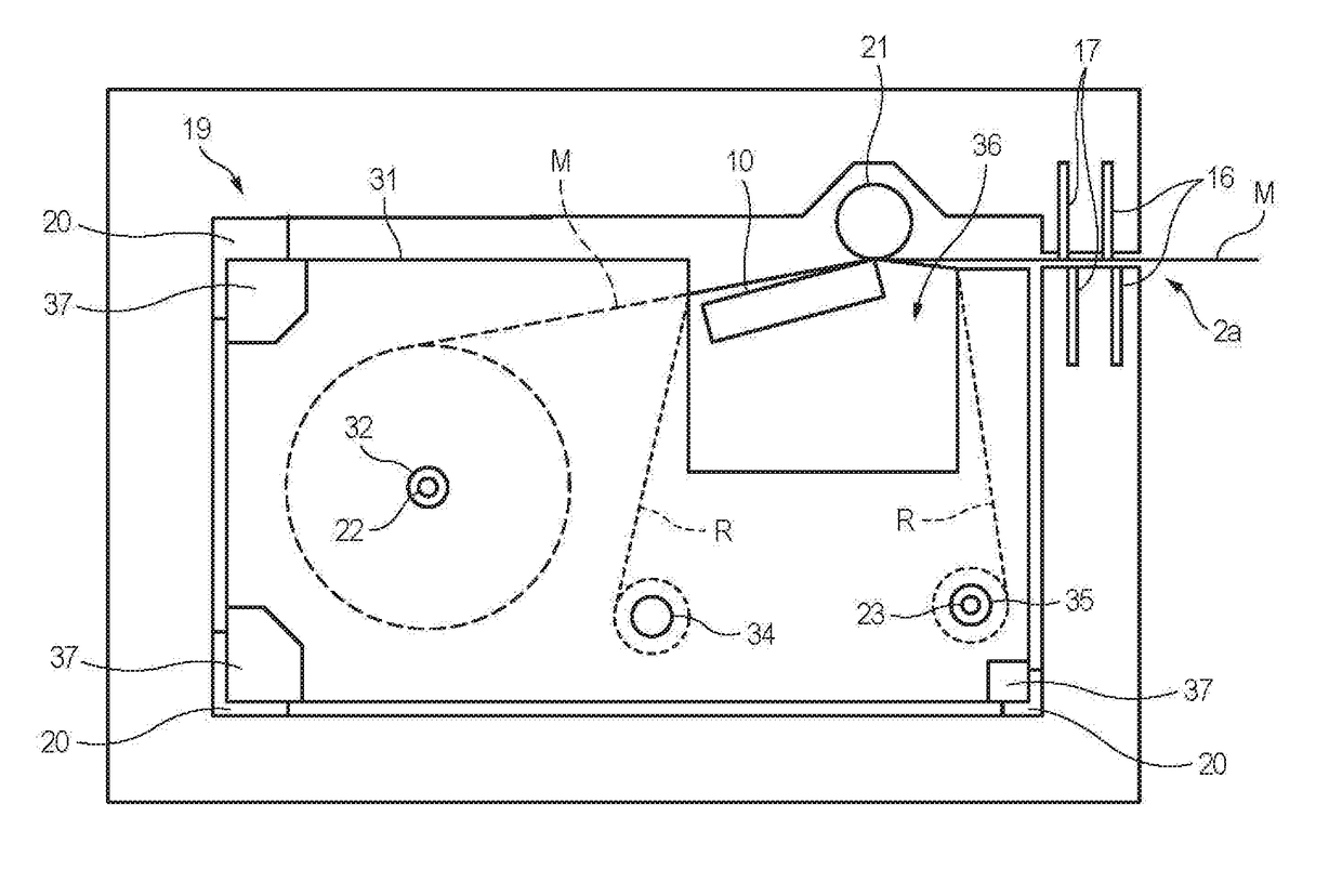
[0033]The printing apparatus 1 is a printing apparatus including a thermal head configured to perform printing on a medium to be printed. For example, the printing apparatus 1 is a label printer configured to perform printing on a long medium to be printed M in a single-path manner.

[0034]In the below, the label printer of a thermal transfer method using an ink ribbon will be exemplified. However, the printing method is not particularly limited. The printing method may be any method in which a sticking may occur. For example, the printing method may be a thermosensitive method using a heat-sensitive paper.

[0035]The medium to be printed M is a long tape member including a base material having an adhes...


PUM


Abstract

A printing apparatus includes a thermal head and a processor. The thermal head prints an image on lines in a medium. The thermal head includes heat-generating elements to generate heat when a voltage is applied thereto in an application time, and the thermal head is controlled to sequentially on print each line. The processor is configured to: determine a specific line among lines based on printing data for printing lines, the specific line being a line estimated to have a possibility of sticking; and adjust the application time of an adjustment target line so as to be shorter than a reference application time, the adjustment target line having at least one line among lines, the at least one line being a line which is to be printed immediately before the specific line, the reference application time being set based on a temperature of the thermal head.

Description

CROSS-REFERENCE TO RELATED APPLICATION[0001]This application is based upon and claims the benefit of priority under 35 USC 119 of Japanese Patent Application No. 2017-046229, filed on Mar. 10, 2017, the entire disclosure of which, including the description, claims, drawings, and abstract, is incorporated herein by reference in its entirety.BACKGROUND OF THE INVENTION1. Field of the Invention[0002]The disclosure relates to a printing apparatus, a printing system, a printing control method, and a computer-readable recording medium.2. Description of the Related Art[0003]In the related art, a printing apparatus configured to control application time to heat-generating elements provided to a thermal head and to transfer ink applied to an ink ribbon to a medium to be printed for printing has been known.[0004]In the printing apparatus having adopted a thermal transfer method, a phenomenon referred to as ‘sticking’ that the ink ribbon is stuck to the thermal head when a rapid temperature ch...

Claims


Application Information

Patent Timeline
Patent Type & Authority Applications(United States)
IPC IPC(8): B41J2/355B41J2/325B41J3/407
CPCB41J2/3558B41J2/325B41J3/4075B41J2/36B41J2/32
Inventor OGAWA, NAOKI
Owner CASIO COMPUTER CO LTD
Why Eureka
Try Eureka