Escape path marking for aircraft

a technology for aircraft and exit path, applied in the direction of aircraft crew accommodation, emergency lighting, mass transit vehicle lighting, etc., can solve the problem that the human eye cannot no longer resolve the structure of the perforated film

Pending Publication Date: 2018-09-13
LUFTHANSA TECH AG
View PDF3 Cites 5 Cited by
  • Summary
  • Abstract
  • Description
  • Claims
  • Application Information

AI Technical Summary

Problems solved by technology

Furthermore, due to sufficiently small passages and small distances between adjacent passages, the human eye can no longer resolve the structure of the perforated film in distances between the eye of the observer and escape path marking typical upo

Method used


Image

  • Escape path marking for aircraft
  • Escape path marking for aircraft
  • Escape path marking for aircraft

Examples


Embodiment Construction

[0019]Embodiments of the present invention provide an escape path marking and an arrangement of escape path marking and floor covering, in which the above-mentioned disadvantages no longer occur or only still occur to a reduced extent.

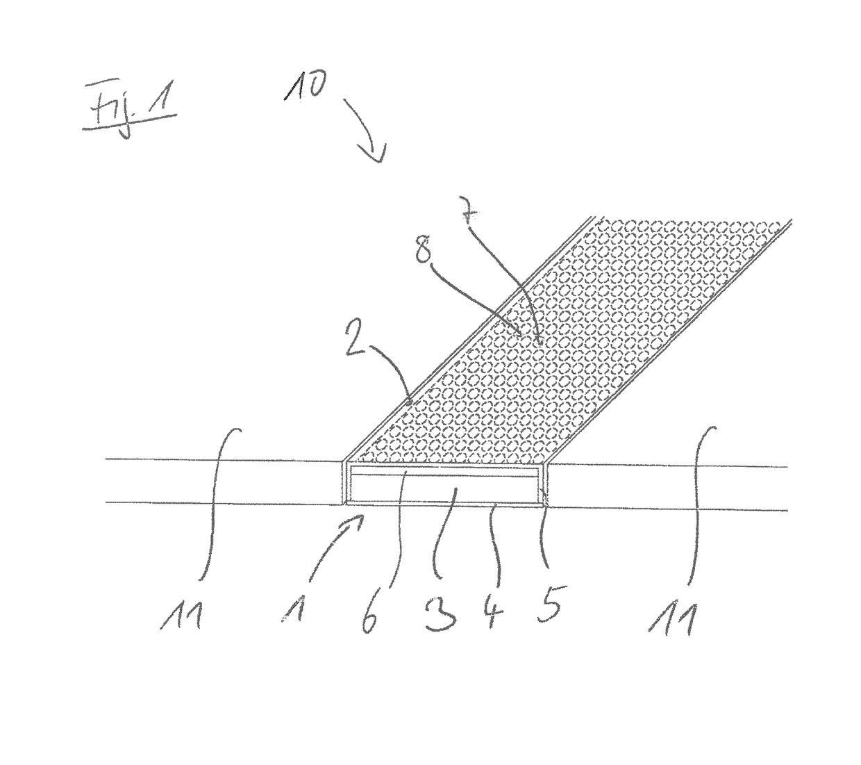
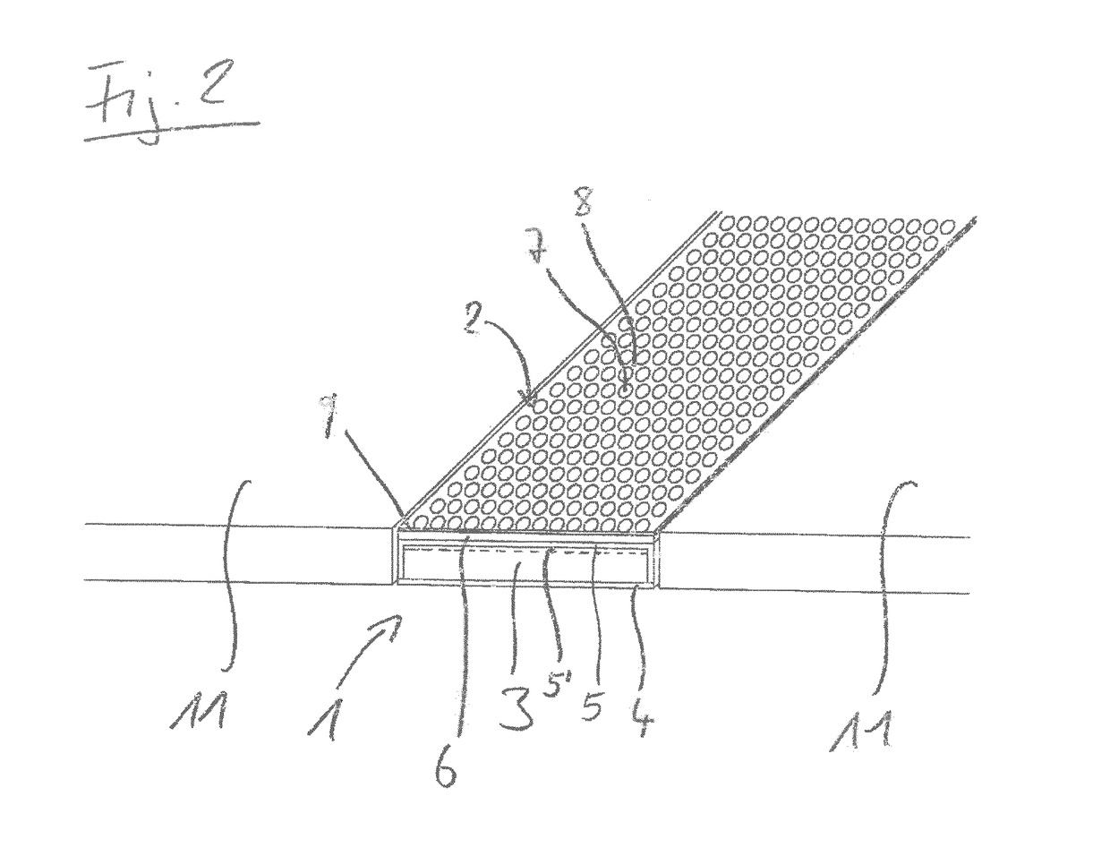
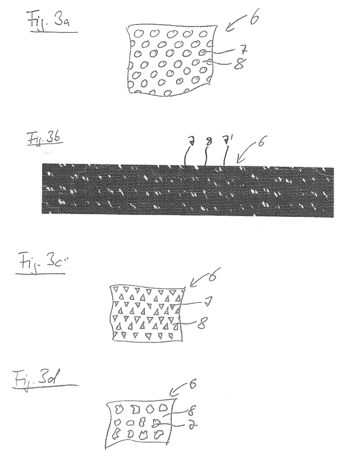
[0020]An embodiment of the present invention accordingly provides an escape path marking for aircraft, comprising a lighting element which luminesces in the dark, and the emitted light of which exits on an outer side of the escape path marking, and a transparent protective element arranged between the lighting element and the outer side of the escape path marking, wherein a planar grid element is provided between the lighting element and the outer side of the escape path marking, which comprises regularly alternating pure-color transparent and opaque regions, and wherein a transparent pigmented element is designed and arranged between the lighting element and the outer side of the escape path marking such that in the event of external illumination acco...


PUM


Abstract

An escape path marking for an aircraft includes a lighting element, which luminesces in a dark environment, and which emits an emitted light which exits at an outer side of the escape path marking. A transparent protective element is arranged between the lighting element and the outer side of the escape path marking. A planar grid element, which comprises regularly alternating pure-color transparent and opaque regions, is arranged between the lighting element and the outer side of the escape path marking. A transparent pigmented element is formed and arranged between lighting element and the outer side of the escape path marking such that in an event of external illumination according to at least one predefined illumination scenario, a predefined first color tone results on the outer side of the escape path marking at the transparent regions of the grid element.

Description

CROSS-REFERENCE TO PRIOR APPLICATIONS[0001]This application is a U.S. National Stage Application under 35 U.S.C. § 371 of International Application No. PCT / EP2016 / 057463 filed on Apr. 6, 2016, and claims benefit to German Patent Application No. DE 10 2015 217 406.9 filed on Sep. 11, 2015. The International Application was published in German on Mar. 16, 2017 as WO 2017 / 041912 A1 under PCT Article 21(2).FIELD[0002]The invention relates to escape path markings for aircraft and also an arrangement of an escape path marking and a floor covering.BACKGROUND[0003]In commercial aircraft, the use of an escape path marking system close to the floor is absolutely necessary to show the path to the emergency exits to passengers in case of emergency in the event of darkness and failure of the cabin lighting.[0004]In addition to electrically operated systems, photoluminescent systems are also known for this purpose. These systems consist of strip-shaped elements, which store energy from the cabin ...

Claims


Application Information

Patent Timeline
IPC IPC(8): B64D47/02B64D11/00B60Q3/46
CPCB64D47/02B64D11/00B60Q3/46B60Q2500/10B64D2011/0038B60Q3/54
Inventor SUTTER, WOLFGANG
Owner LUFTHANSA TECH AG
Why Eureka
Try Eureka