Unlock instant, AI-driven research and patent intelligence for your innovation.

Assembly for connecting a plug to an electronic device housing panel baseplate, integrating a thermal regulation means, and associated plug and baseplate

Active Publication Date: 2018-09-13
RADIALL SA
View PDF7 Cites 14 Cited by
  • Summary
  • Abstract
  • Description
  • Claims
  • Application Information

AI Technical Summary

Benefits of technology

The active thermal regulation module prevents damage or malfunction to optoelectronic or electronic transceivers no matter the environmental conditions. This is achieved by detecting the temperature and controlling it through a Peltier module or an additional temperature sensor. Additionally, the plug locking force is uniformly transmitted to the gasket, which compresses the seal to ensure a secure connection.

Problems solved by technology

It turns out however that using such a plug as a transceiver with a transceiver of QSFP / QSFP+ type in a remote radio head (RRH) of a base station produces a large amount of heat.
In addition, the other components of the device generally themselves generate a large amount of heat.
Furthermore, the lower operating temperature limit for this kind of transceiver is generally 0° C., and it will not operate correctly at temperatures lower than this.
One solution could consist in integrating a cooling apparatus into the inside of the electronic device, i.e. on the side of the electronic circuit board, but such an apparatus would be too bulky and expensive.
It would also be ineffective as the frame of the device alone would not be sufficient to dissipate the heat generated by all of the components to the outside of the device.
By contrast, when the environment outside the electronic device is at very low temperatures, there remains a risk of the optoelectronic transceiver or electronic transceiver no longer being within its operating temperature range.

Method used


Image

  • Assembly for connecting a plug to an electronic device housing panel baseplate, integrating a thermal regulation means, and associated plug and baseplate
  • Assembly for connecting a plug to an electronic device housing panel baseplate, integrating a thermal regulation means, and associated plug and baseplate
  • Assembly for connecting a plug to an electronic device housing panel baseplate, integrating a thermal regulation means, and associated plug and baseplate

Examples


Embodiment Construction

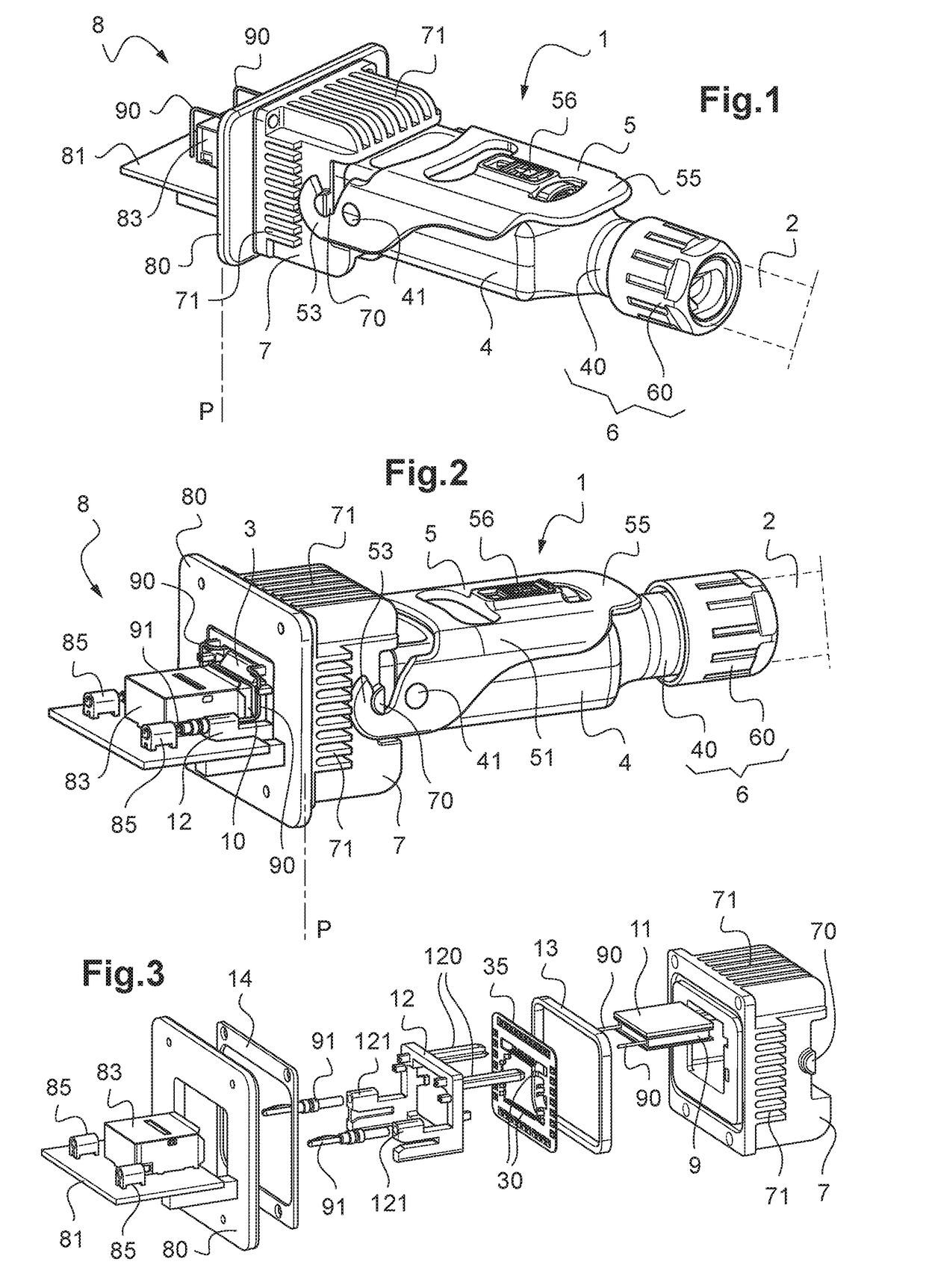
[0061]Other advantages and features of the invention will become more apparent upon reading the detailed description of exemplary implementations of the invention, given by way of nonlimiting illustration, and with reference to the following figures, in which:

[0062]FIG. 1 is a perspective view of a first exemplary connection assembly according to the invention, with a plug integrating an optoelectronic transceiver of ‘QSFP / QSFP+’ type in a configuration in which it is connected and locked to a receptacle of an electronic device housing panel, the optoelectronic transceiver of the plug being connected to the contact of the electronic component mounted on the surface of the printed circuit board of the electronic device, the receptacle housing and holding a Peltier module according to the invention supplied with power from the printed circuit board;

[0063]FIG. 2 is a view analogous to FIG. 1, with a different electric power supply for the Peltier module;

[0064]FIG. 3 is an exploded view...


PUM


Abstract

The application defines a suitable active thermal interface between the optoelectronic or electronic transceiver and the outside environment that is perfectly integrated into the plug or the connection receptacle.

Description

[0001]The present application claims priority to French Patent Application No. 17 519 78, filed Mar. 10, 2017. The contents of this application are incorporated herein by reference in its entirety.TECHNICAL FIELD[0002]The present invention relates to an assembly for connecting a plug to a receptacle of a housing panel of an electronic device.[0003]The plug is intended to be mounted on at least one cable bearing one or more contacts, which are an optoelectronic converter interface, also called a transceiver, of SFP / SFP+, QSFP / QSFP+ or XFP type, or else an electronic transceiver interface of RJ45 type.[0004]The invention is applicable to plugs for connection to receptacles of electronic devices that implement a plurality of optical and / or electrical paths with connections, such as are found in an outdoor environment and / or in severe conditions, in particular in telecommunications installations such as relay antennas in mobile telephony, in high-throughput data transmission networks to...

Claims


Application Information

Patent Timeline
IPC IPC(8): G02B6/42
CPCG02B6/4271G02B6/423G02B6/428G02B6/4246G02B6/4268H01R12/716H01R13/502H01R13/66H01R13/665H01R13/6683H01R13/7137G02B6/4284H01R13/508H01R13/6596H01R13/6658
Inventor DUPEUX, M. BENO TLOMUSCIO, DOMINIQUEBOURGEAS, FABIENBADIQUE, VIVIEN
Owner RADIALL SA