Siphon-type heat dissipation device and display device with same

a heat dissipation device and display device technology, applied in the direction of indirect heat exchangers, light-emitting elements or other components of the electronic display device, can solve the problems of insufficient heat dissipation efficiency unsatisfactory heat dissipation function of the conventional heat dissipation plate or thermally conductive plate, etc., to achieve good heat dissipation efficiency

Inactive Publication Date: 2018-09-13
AURAS TECH
View PDF5 Cites 11 Cited by
  • Summary
  • Abstract
  • Description
  • Claims
  • Application Information

AI Technical Summary

Benefits of technology

[0005]For solving the drawbacks of the conventional technology, the present invention provides a siphon-type heat dissipation device and a display device with the siphon-type heat dissipation device. The siphon-type heat dissipation device has good heat-conducting efficacy and good heat-dissipating efficacy. The siphon-type heat dissipation device is capable of absorbing the heat energy from the heat source and directly conducting and dissipating the heat energy. Consequently, the heat dissipating efficiency is enhanced.

Problems solved by technology

If the heat energy is not effectively removed, the light-emitting element or other component of the electronic display device is possibly damaged because of the overheated condition.
However, the heat dissipating function of the conventional heat dissipation plate or thermally conductive plate is usually unsatisfied.
In case that a large amount of heat energy is generated by a large-sized screen or a great number of heat sources, the heat dissipation efficiency of the conventional heat dissipation plate or thermally conductive plate is insufficient.

Method used


Image

  • Siphon-type heat dissipation device and display device with same
  • Siphon-type heat dissipation device and display device with same
  • Siphon-type heat dissipation device and display device with same

Examples


Embodiment Construction

[0050]The present invention will now be described more specifically with reference to the following embodiments and accompanying drawings.

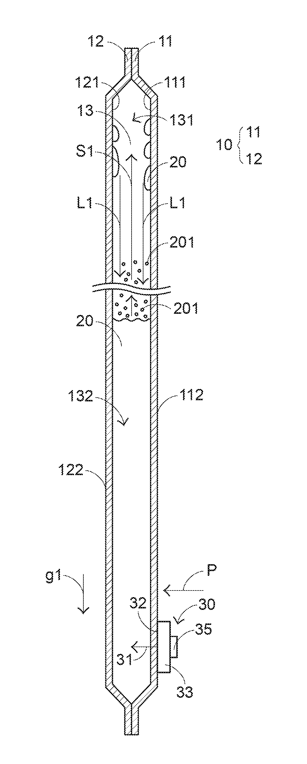
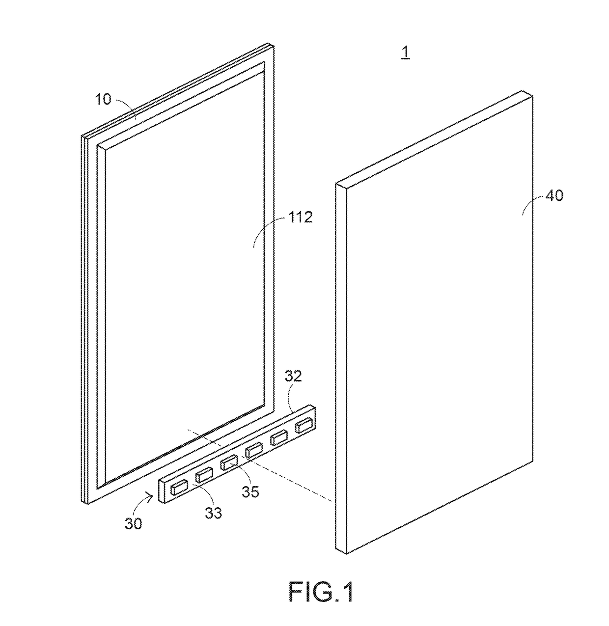
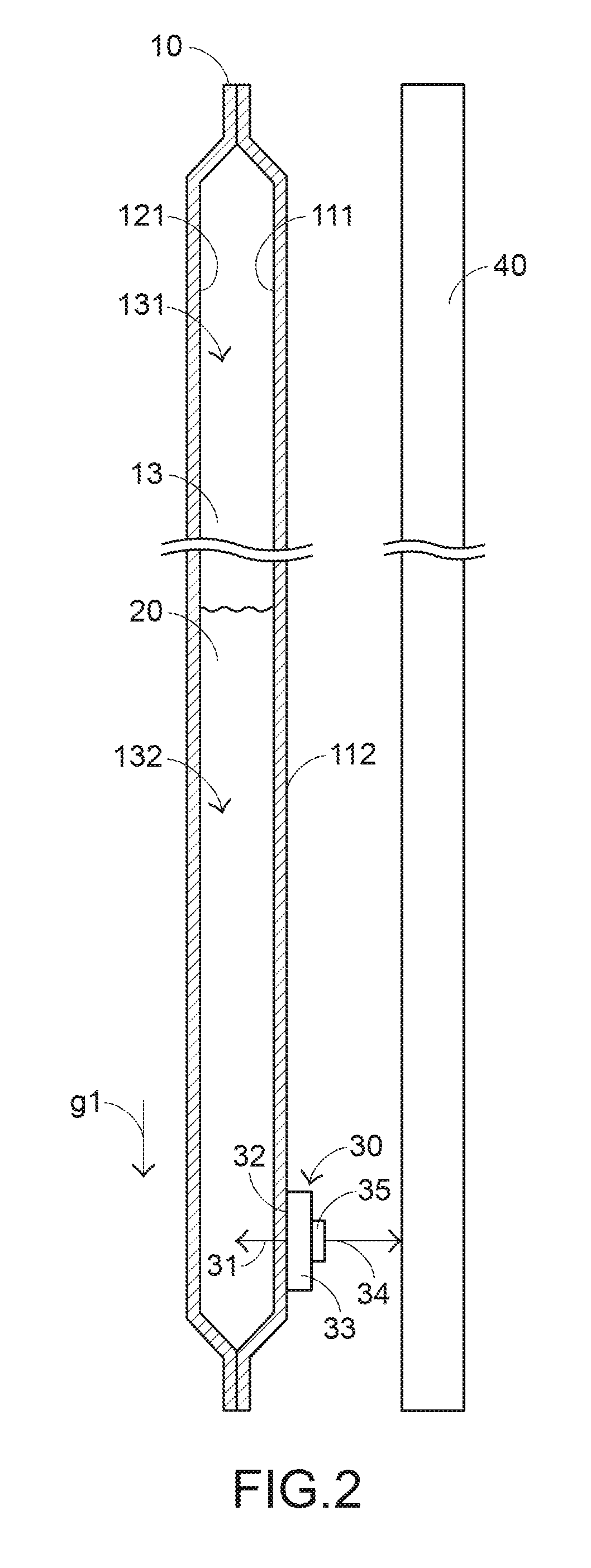
[0051]A first embodiment of the present invention will be described as follows. FIG. 1 is a schematic perspective and exploded view illustrating a display device according to a first embodiment of the present invention. FIG. 2 is a schematic cross-sectional view illustrating the display device according to the first embodiment of the present invention. The display device 1 comprises a display panel 40, a siphon-type heat dissipation device 10 and a heat source 30. The siphon-type heat dissipation device 10 comprises a first inner surface 111 and a second inner surface 121, and contains a working liquid 20. An accommodation space 13 is formed between the first inner surface 111 and the second inner surface 121. The accommodation space 13 comprises an upper portion 131 and a lower portion 132. The heat source 30 comprises a heat transfer surface 32,...


PUM


Abstract

A siphon-type heat dissipation device includes a first plate body, a second plate body and a working liquid. An accommodation space is formed between the first plate body and the second plate body. The working liquid is accumulated in a lower portion of the accommodation space. A heat source is attached on the siphon-type heat dissipation device. After a heat energy generated by the heat source is transferred into the working liquid, the heat energy is absorbed by the working liquid, so that a portion of the working liquid is vaporized into a working vapor. After the working vapor ascends to an upper portion of the accommodation space, the heat energy is dissipated to surroundings, and the working vapor is condensed and changed into the working liquid. The working liquid flows back to the lower portion of the accommodation space.

Description

FIELD OF THE INVENTION[0001]The present invention relates to a heat dissipation plate, and more particularly to a siphon-type heat dissipation device for an electronic device and a display device with the siphon-type heat dissipation device.BACKGROUND OF THE INVENTION[0002]Nowadays, an electronic display device such as a LCD TV or a large-sized screen is usually equipped with a display panel and a heat source. For example, the heat source is a light-emitting element, a light bar or a light emitting diode. When a light beam generated by the heat source is projected to the display panel, an image is shown on the display panel. Since the heat source continuously emits the light beam, a large amount of heat energy is also generated. Generally, the electronic display device is equipped with a heat dissipation device to dissipate the heat energy away. If the heat energy is not effectively removed, the light-emitting element or other component of the electronic display device is possibly d...

Claims


Application Information

Patent Timeline
Patent Type & Authority Applications(United States)
IPC IPC(8): H05K7/20F28F3/12F28F13/00F28F3/02F28F9/007
CPCH05K7/2099F28F3/12F28F13/003F28F3/022H05K7/20963H05K7/20336H05K7/20481F28F2225/04H05K7/20972F28F9/0075F28F3/025F28F3/044F28F3/06F28F21/081F28D9/0031F28D15/0233H01L23/427H01L25/0753H01L33/648F21V29/00
Inventor WU, AN-CHIHFAN, MU-SHUCHEN, CHIEN-YU
Owner AURAS TECH
Why Eureka
Try Eureka