Abnormality detection apparatus and machine learning apparatus

a detection apparatus and machine learning technology, applied in the direction of program control, instruments, testing/monitoring control systems, etc., can solve problems such as abnormality cannot be detected, machining failure, and machining failur

Inactive Publication Date: 2018-09-20
FANUC LTD
View PDF2 Cites 22 Cited by
  • Summary
  • Abstract
  • Description
  • Claims
  • Application Information

AI Technical Summary

Benefits of technology

[0005]Accordingly, an object of the present invention is to provide an abnormality detection apparatus and a machine learning apparatus which can detect a machining state abnormality of a machine tool irrespective of machining details.

Problems solved by technology

In machine tools, tool wear or breakage, machining load variation, a change in a machining environment such as cutting fluid, disturbance, or the like may cause a machining failure.
There are cases where the remachining of a machined workpiece causes a machining failure.
However, in the technique disclosed in Japanese Patent Application Laid-Open No. 2007-52797, there is a problem in that sampling points need to be set in accordance with a specific program and machining details in advance and an abnormality cannot be detected independently of machining details and the like.
Further, in the technique disclosed in Japanese Patent Application Laid-Open No. 05-285788, there is a problem in that predetermined operation needs to be executed at the time of inspection and this technique cannot be applied to abnormality detection at the time of machining.

Method used


Image

  • Abnormality detection apparatus and machine learning apparatus
  • Abnormality detection apparatus and machine learning apparatus
  • Abnormality detection apparatus and machine learning apparatus

Examples


first embodiment

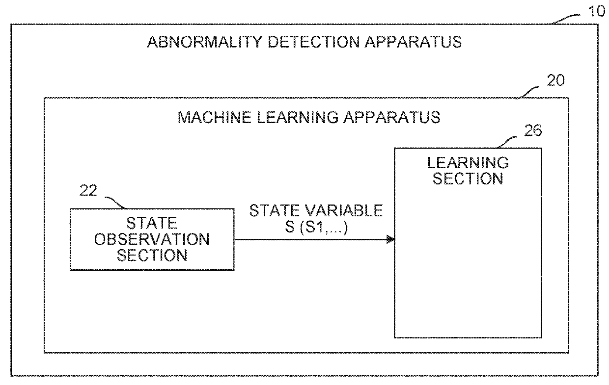
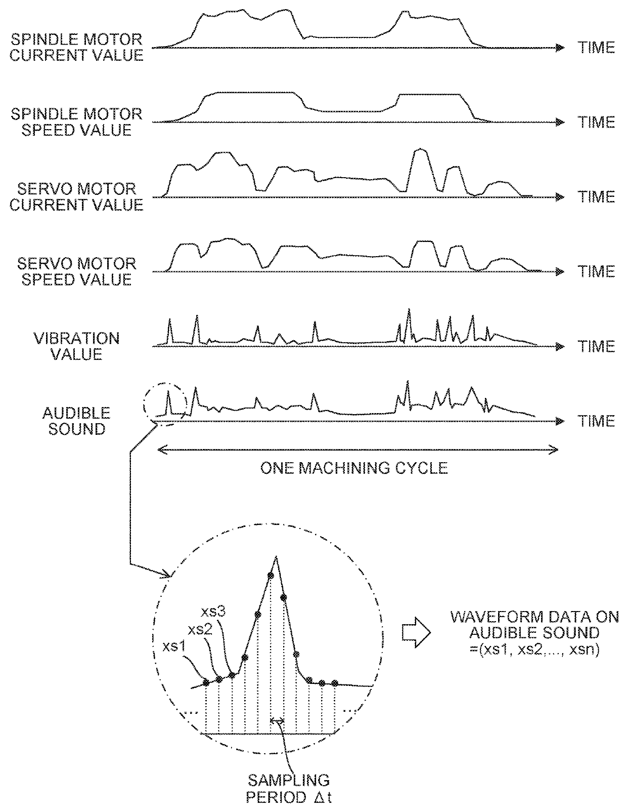
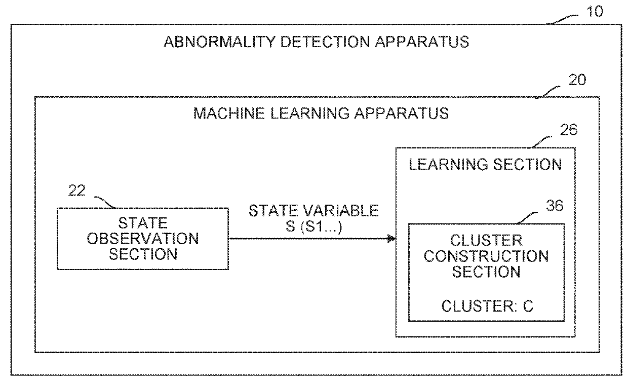
[0027]FIG. 1 is a schematic functional block diagram of an abnormality detection apparatus 10 according to a The abnormality detection apparatus 10 includes a machine learning apparatus 20 including software (learning algorithm and the like) and hardware (such as a CPU of a computer) for learning, by so-called machine learning by itself, waveform data for one machining cycle or a desired period concerning physical quantity values (current values and speed values of a spindle motor and a servo motor, vibration value detected from a machine tool, audible sound, and the like) detected in machining performed in a machine tool normally operating. Contents that the machine learning apparatus 20 of the abnormality detection apparatus 10 learns correspond to a model structure of waveform data for one machining cycle or a desired period concerning physical quantity values detected from a machine tool normally operating in machining.

[0028]As indicated by functional blocks in FIG. 1, the mach...

second embodiment

[0050]FIG. 5 shows an abnormality detection apparatus 40 according to a The abnormality detection apparatus 40 includes a machine learning apparatus 50, and a state data acquisition section 42 for acquiring waveform data S1 on a state variable S observed by the state observation section 22 as state data S0. The state data acquisition section 42 can acquire the state data S0 from the aforementioned plurality of measurement apparatuses attached to the machine.

[0051]The machine learning apparatus 50 of the abnormality detection apparatus 40 includes software (arithmetic algorithm or the like) and hardware (a CPU of a computer or the like) for outputting a determination as to whether the current operation of the machine tool is normal operation to an operator based on the learned waveform data concerning values detected when the machine tool is normally operating, in addition to software (learning algorithm or the like) and hardware (a CPU of a computer or the like) for learning wavefo...


PUM


Abstract

An abnormality detection apparatus includes a machine learning apparatus for learning waveform data concerning a physical quantity detected when a machine tool is normally operating. The machine learning apparatus observes the waveform data concerning the physical quantity detected when the machine tool is normally operating, as a state variable indicating a current environmental state, and learns a feature of the waveform data concerning the physical quantity detected when the machine tool is normally operating, using the observed state variable.

Description

BACKGROUND OF THE INVENTION1. Field of the Invention[0001]The present invention relates to a machining state abnormality detection apparatus and a machine learning apparatus.2. Description of the Related Art[0002]In machine tools, tool wear or breakage, machining load variation, a change in a machining environment such as cutting fluid, disturbance, or the like may cause a machining failure. There are cases where the remachining of a machined workpiece causes a machining failure. These cannot be said to be a normal machining state. It is desired that these machining state abnormalities are detected so that the occurrence of a machining failure can be determined before the occurrence thereof.[0003]As a prior art technique for detecting a machining state abnormality, for example, Japanese Patent Application Laid-Open No. 2007-52797 discloses a technique that sets sampling points in accordance with a program and machining details in advance, and compares data acquired when machining is...

Claims


Application Information

Patent Timeline
Patent Type & Authority Applications(United States)
IPC IPC(8): B23Q17/00G06N99/00G06N20/00
CPCB23Q17/007G06N99/005B23Q2717/00G01D21/02G05B19/406G05B19/4065G07C3/005G06N20/00G06N3/088G05B2219/49307G05B23/0229G06N3/045G05B19/00G05B19/4063G05B19/404
Inventor TAMAI, TAKAYUKIOKUDA, SHINJI
Owner FANUC LTD
Why Eureka
Try Eureka