Intelligent POD Management and Transport

Active Publication Date: 2018-09-20
EVANS MICHAEL STEWARD
View PDF6 Cites 26 Cited by
  • Summary
  • Abstract
  • Description
  • Claims
  • Application Information

AI Technical Summary

Benefits of technology

[0013]In one embodiment the trolley further comprises on-board control circuitry, enabled to start, stop and change speed of the trolley traveling on the rail set. Also, in one embodiment, the on-board control circuitry further comprises wireless communication circuitry. Also, in one embodiment the system further comprises a control site external to the trolley, having control circuitry including a central processing unit (CPU) and wireless communication circuitry, and wherein the control circuitry of the control site external to the trolley is enabled to control the trolley and switching elements to divert the trolley from one set of rails to another. In another embodiment the pod has, in addition to the upward-facing latching interface, a downward-facing latching interface at a lower extremity of the pod, enabled to latch to an interface of a wheeled smart chassis, such that a pod may be transferred from the trolley to a smart chassis, to be driven along ground surfaces. And in one embodiment the trolley is adapted to latch to and to carry a plurality of pods.
[0014]In one embodiment of the system there is further a four-pod trolley. Also, in one embodiment the system further comprises an elevator platform upon which a pod is placed, which, by raising the elevator platform a pod is latched to a trolley. In another embodiment latches are implemented on forward and rearward interfaces of the trolley, such that trolleys are enabled to connect to and disconnect from other trolleys, forming traveling trains of trolleys. And in one embodiment the upward-facing latching interface of the pod is compatible with a downward-facing latching interface of a drone, such that the pod may be carried by either the drone or the trolley.

Problems solved by technology

Secondly, for environmental reasons, because batteries plus electric motors eliminate the need for fossil fuels and are now cost competitive.

Method used


Image

  • Intelligent POD Management and Transport
  • Intelligent POD Management and Transport
  • Intelligent POD Management and Transport

Examples


Embodiment Construction

[0065]In various embodiments described in enabling detail herein, the inventor provides a unique drone enabled transport system that includes self-navigating chassis carrying pods, that may carry passengers or parcels. The present invention is described using the following examples, which may describe more than one relevant embodiment falling within the scope of the invention.

Single Pod Drones

[0066]What is generally proposed as unique in embodiment of the invention is a drone and pods which may separate from each other. All pods in this system may conform to a standardized drone-pod attaching system, and the pods may be used to carry passengers, parcels, or both.

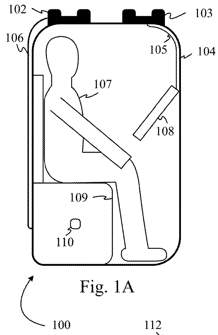
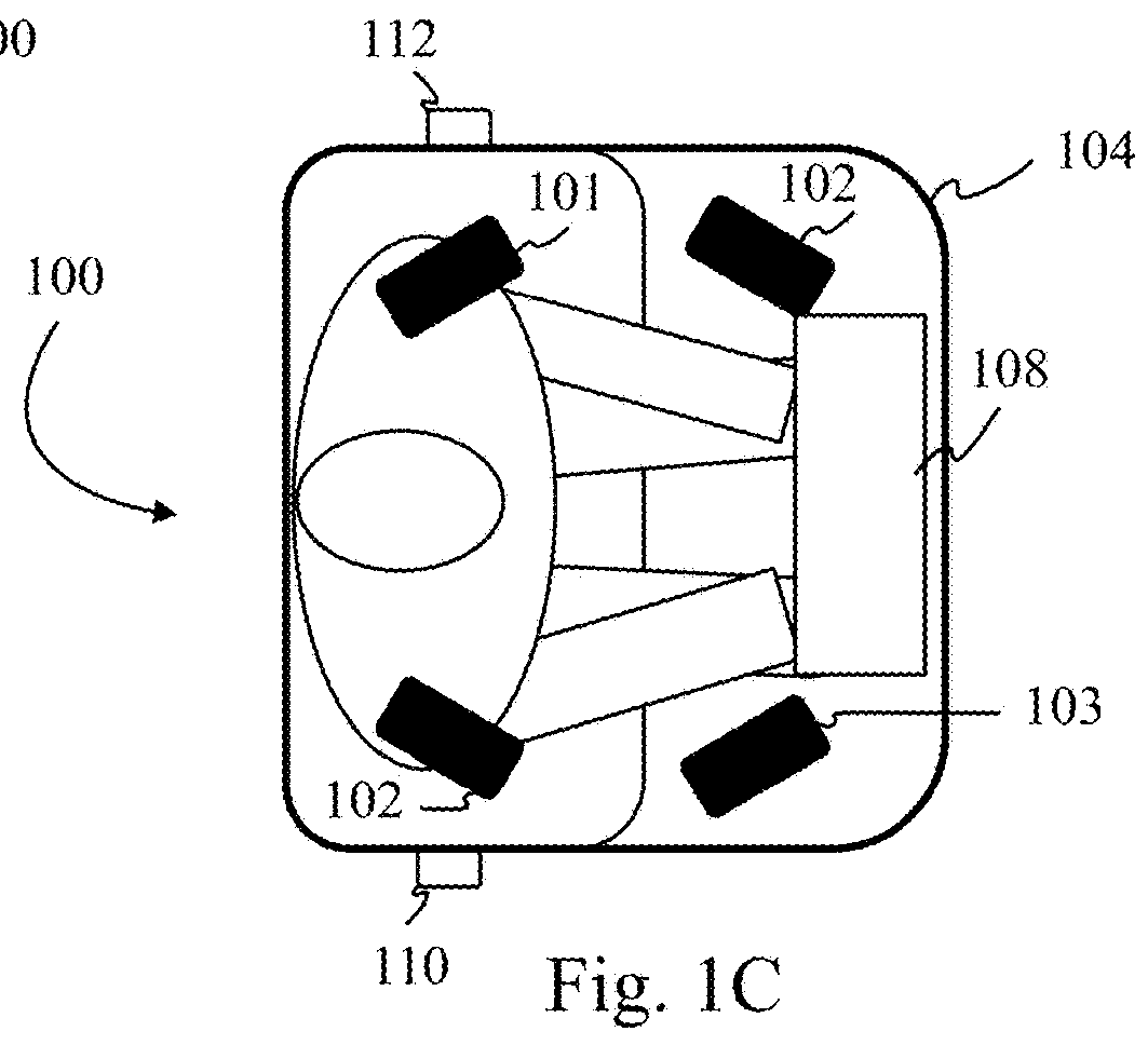
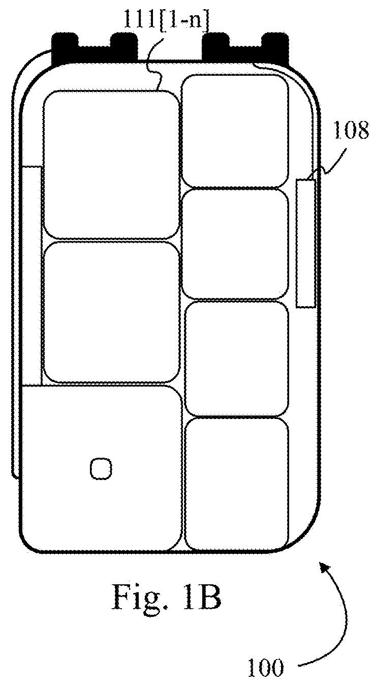
[0067]FIGS. 1A to 1C are illustrations of a pod 100 according to one embodiment of the present invention. Pod 100 comprises a capsule about the height of a passenger 107 while seated and around 1 m×1m (3′×3′) in width and depth. These dimensions are exemplary and may vary considerably. Pod 100 may have four latches on its ro...


PUM


Abstract

A transport system has a first set of substantially parallel rails supported above ground level by support structures, a trolley having wheels mounted to a frame with the wheels engaging the rails, at least one wheel powered to move the trolley along the set of rails, a portion of the frame depending between the rails to a level below the rails, and a downward-facing latching interface on the depending portion of the frame, and a pod enabled to carry a passenger or parcels, or both, engaged by an upward-facing latching interface to the downward-facing latching interface of the trolley, such that, as the trolley travels along the rail set, the pod is carried along below the rail set.

Description

CROSS-REFERENCE TO RELATED DOCUMENTS[0001]The present invention is a Continuation-in-Part of, and claims priority to, U.S. patent application Ser. No. 15 / 960,975, filed Apr. 24, 2018, which is a CIP of Ser. No. 15 / 456,311, entitled “Drone Transport System”, filed on Mar. 10, 2017, which claims priority to provisional patent application (PPA) 62 / 443,187, filed Jan. 6, 2017.[0002]The present invention is a Continuation-in-Part of, and claims priority to, U.S. Ser. No. 15 / 950,018, filed Apr. 10, 2018, which is a CIP of U.S. Ser. No. 15 / 260,670, filed Sep. 9, 2016 and issued on Apr. 10, 2018 as U.S. Pat. No. 9,937,808.[0003]The present application also claims priority to provisional application 62 / 613,285 filed Jan. 3, 2018, provisional application 62 / 639,205, filed Mar. 6, 2018, and to provisional application 62 / 651,496, filed Apr. 2, 2018. All disclosure of the parent applications is incorporated herein at least by reference.BACKGROUND OF THE INVENTION1. Field of the Invention[0004]Th...

Claims


Application Information

Patent Timeline
Patent Type & Authority Applications(United States)
IPC IPC(8): B61B3/02E01B25/22B61B1/02
CPCB61B3/02E01B25/22B61B1/02B61B13/00B60L5/39B60M1/30B64C39/024B64D1/22B64C2211/00B62D31/003B62D31/025B62D47/006B64U10/13B64U50/19B64U30/20B64U2101/60
Inventor EVANS, MICHAEL STEWARD
Owner EVANS MICHAEL STEWARD
Why Eureka
Try Eureka