Vehicle lower portion structure

a technology of lower portion and lower portion, which is applied in the direction of vehicle sub-unit features, electric propulsion mounting, transportation and packaging, etc., can solve the problems of difficulty in sufficiently ensuring, damage to the battery (the battery cells) itself, etc., and achieve the effect of improving impact absorption performance and simple structur

Active Publication Date: 2018-09-27
TOYOTA JIDOSHA KK
View PDF27 Cites 28 Cited by
  • Summary
  • Abstract
  • Description
  • Claims
  • Application Information

AI Technical Summary

Benefits of technology

[0020]According to the above-described aspects, the vehicle lower portion structure of the present disclosure ...

Problems solved by technology

Therefore, it can be thought that it is difficult to sufficiently ensure the impact absorbing perfo...

Method used


Image

  • Vehicle lower portion structure
  • Vehicle lower portion structure
  • Vehicle lower portion structure

Examples


Embodiment Construction

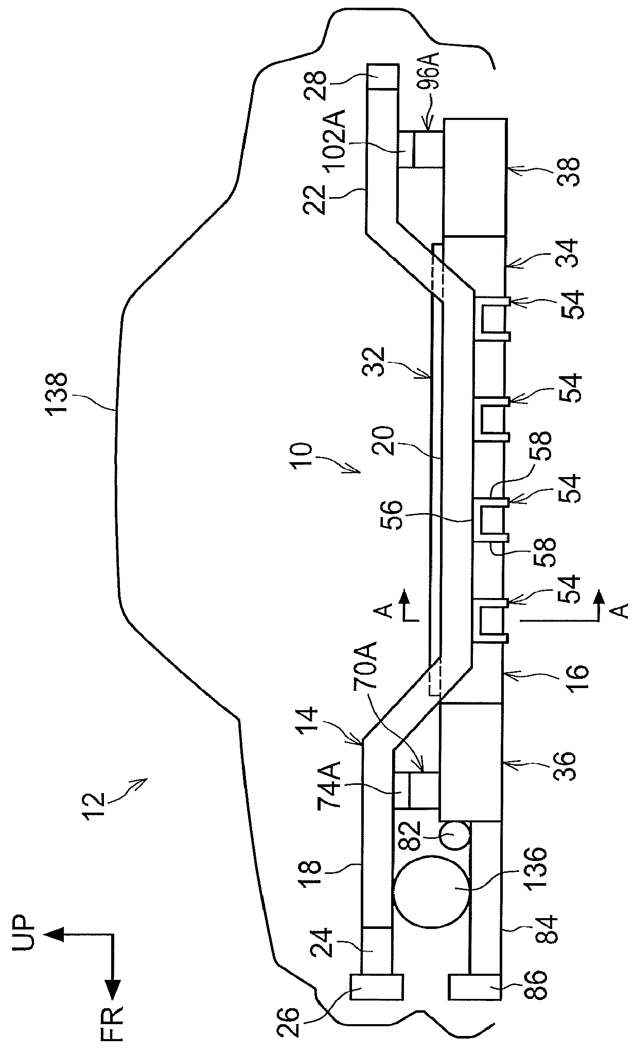
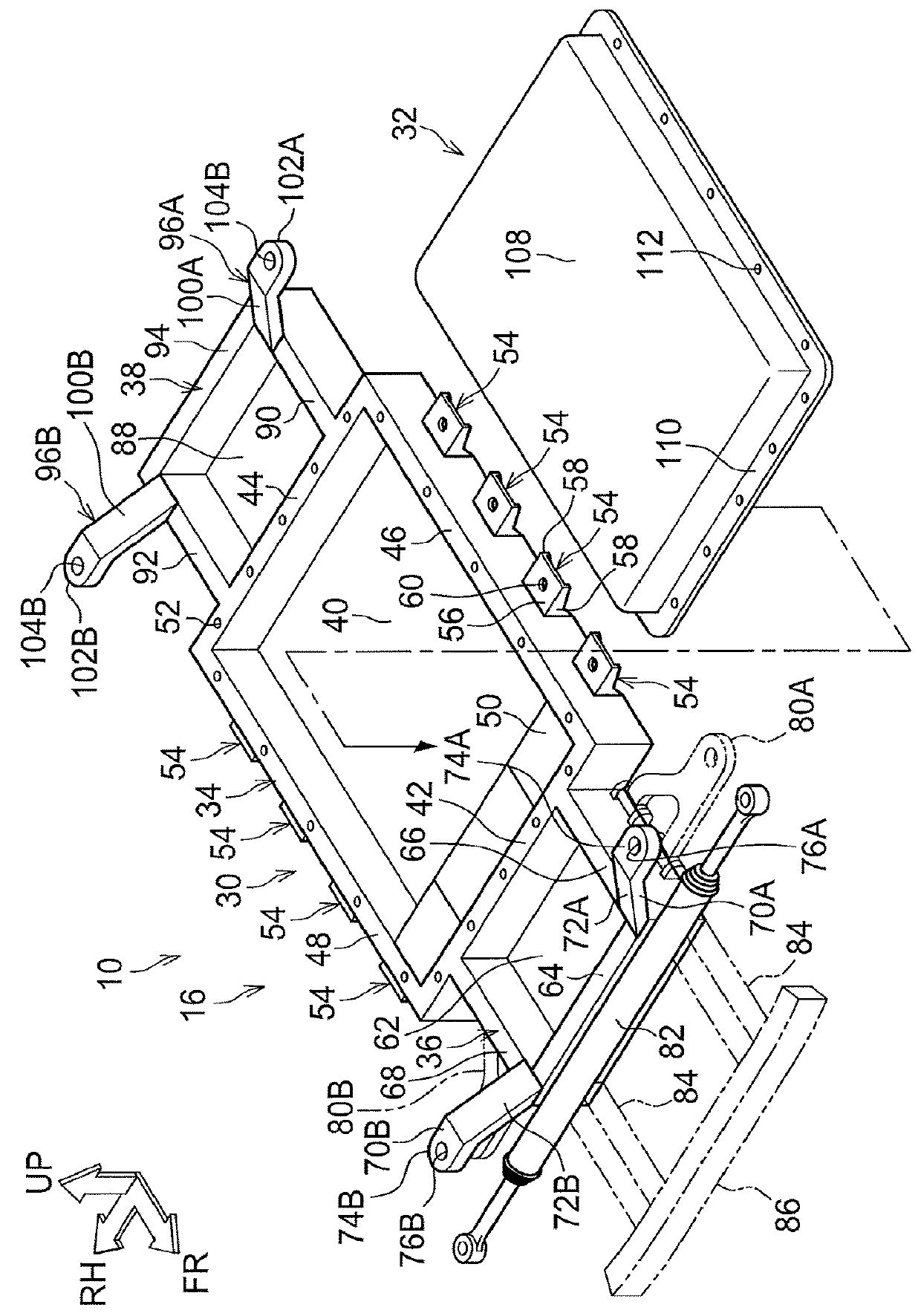
[0025]A vehicle lower portion structure according to a first embodiment of the present disclosure is described with reference to FIG. 1 through FIG. 3. Note that the vehicle vertical direction upper side is indicated by arrow UP, the vehicle longitudinal direction front side is indicated by arrow FR, and the vehicle transverse direction right side is indicated by arrow RH. Further, in FIG. 2, illustration of side members 14 and rockers 12 is omitted.

[0026]A vehicle 12 to which a vehicle lower portion structure 10 is applied is described first.

[0027]As shown in FIG. 1, the vehicle 12 is an electric car, and has the side members 14 that are vehicle frame members, and a battery pack 16 that is supported at the side members 14.

[0028]As shown in FIG. 1, the side members 14 (only one of which is illustrated) are a pair of left and right vehicle frame members that extend from the front end to the rear end of the vehicle at the vehicle transverse direction both side portions of the vehicle....


PUM


Abstract

The present disclosure provides a vehicle lower portion structure including: a case main body portion, disposed at a vehicle lower side of a vehicle cabin floor and including a bottom wall and peripheral walls that extend toward a vehicle upper side from a peripheral edge portion of the bottom wall, and accommodating a battery at an interior thereof; a front portion extending portion formed integrally with the case main body portion at a vehicle front side of the case main body portion, at the peripheral wall that is at a vehicle front side of the case main body portion; and an impact absorbing portion, extending in a vehicle longitudinal direction and deforming due to input of collision load from a vehicle front side, a rear end portion of the impact absorbing portion being connected to a vehicle front side region of the front portion extending portion.

Description

CROSS-REFERENCE TO RELATED APPLICATION[0001]This application claims priority under 35 USC 119 from Japanese Patent Application No. 2017-057970, filed on Mar. 23, 2017, the disclosure of which is incorporated by reference herein.BACKGROUNDTechnical Field[0002]The present disclosure relates to a vehicle lower portion structure.Related Art[0003]In a battery-mounted vehicle such as an electric car or the like, plural batteries are mounted beneath the vehicle cabin floor in a state of being accommodated in a battery case. Therefore, a portion having a large load (mass) exists beneath the vehicle cabin. Accordingly, in a case in which the vehicle is involved in a front collision with an obstacle or the like, a large inertial force may be applied to the battery unit and to the vehicle cabin that is positioned thereabove, and the vehicle cabin may easily deform.[0004]Thus, various proposals have been made in order to reduce the impact force that is applied to the vehicle cabin in such a bat...

Claims


Application Information

Patent Timeline
IPC IPC(8): B60K1/04B62D25/20
CPCB60K1/04B62D25/2018B60K2001/0411B60K2001/0438B62D21/152B62D25/08B60Y2306/01B62D21/07B62D24/00
Inventor AJISAKA, SATOSHI
Owner TOYOTA JIDOSHA KK
Why Eureka
Try Eureka