Electric retractable view device for vehicle

a technology of electric retractable and view device, which is applied in the direction of friction gearing, vehicle components, gearings, etc., can solve problems such as visibility deterioration, and achieve the effects of reducing the rotation and reducing the wear of the first worm

Active Publication Date: 2018-10-04
MURAKAMI CORP
View PDF1 Cites 5 Cited by
  • Summary
  • Abstract
  • Description
  • Claims
  • Application Information

AI Technical Summary

Benefits of technology

[0007]An electric retractable view device for a vehicle according to this invention includes: a view device rotating section including a view section body mounted therein, a rotation support section that supports the view device rotating section in such a manner that the view device rotating section is rotatable relative to a vehicle body in a direction around a predetermined rotation axis, and an electric driving mechanism that electrically drives the view device rotating section to rotate in the direction around the rotation axis and thereby moves the view device rotating section to either of a retracted position and an extended position, and the electric driving mechanism includes a motor, and a power transmission mechanism that transmits a drive force of the motor to the view device rotating section to rotate the view device rotating section in the direction around the rotation axis, the power transmission mechanism includes a double-threaded worm, and one or more motor-side worms disposed on the motor side relative to the double-threaded worm, and each of the one or more motor-side worms is a single-threaded worm. The electric retractable view device for a vehicle according to this invention enables reduction in rotation of the double-threaded worm and gears and the like on the upstream side thereof, compared to an electric retractable view device for a vehicle in which the double-threaded worm is a single-threaded worm, if moving speeds of both view device rotating sections are the same. As a result, wear of the double-threaded worm and the gears and the like on the upstream side thereof can be reduced.
[0008]In this invention, it is possible that: the rotation support section includes a shaft provided in a standing manner on the vehicle body side; the view device rotating section is supported by the shaft so as to be rotatable in a direction around an axis of the shaft; the motor is mounted in the view device rotating section; and the power transmission mechanism includes a mechanism that transmits the drive force of the motor to the shaft to rotate the view device rotating section in the direction around the axis of the shaft. In this case, it is possible that: the power transmission mechanism includes a first worm wheel fitted on an outer circumference of the shaft and thereby coupled to the shaft, and a first worm that engages with the first worm wheel and thereby provides a first worm drive; and the first worm is the double-threaded worm. This electric retractable view device for a vehicle enables reduction in rotation of the first worm and the gears and the like on the upstream side thereof, compared to an electric retractable view device for a vehicle in which the first worm is a single-threaded worm, if the moving speeds of both view device rotating sections are the same, enabling reduction of wear of the first worm and the gears and the like on the upstream side of the first worm.
[0009]In this invention, it is possible that: the power transmission mechanism includes a second worm connected to a motor shaft of the motor, a second worm wheel that engages with the second worm and thereby provides a second worm drive, and an intermediate transmission mechanism that transmits rotation of the second worm wheel to the first worm; and the second worm is the only motor-side worm in the power transmission mechanism. According to this electric retractable view device for a vehicle, rotation of the motor may be slow, compared to an electric retractable view device for a vehicle in which a third worm is disposed between the second worm and the first worm, if the moving speeds of both rotating sections are the same, and thus, wear of the second worm drive can be reduced. In particular, if the intermediate transmission mechanism includes an axle of the first worm that coaxially directly connects the second worm wheel and the first worm, the second worm wheel may rotate at a low speed that is the same as that of the first worm, enabling further reduction of wear of the second worm drive.
[0010]In this invention, it is possible that a lead angle of the double-threaded worm is set to 8 to 15 degrees. In general, a double-threaded worm has a large lead angle and is thus used for a purpose of preventing self-locking (that is, enabling the worm to be rotated from a worm wheel), and is not used for a purpose that needs self-locking. In an electric retractable view device for a vehicle, if self-locking is not available, when the vehicle is running, inconveniences such as deterioration in visibility by backlash of the rotating section and / or unintended movement of the position of the rotating section caused due to, e.g., vibration of the vehicle occur. As a result of the lead angle of the double-threaded worm being set to 8 to 15 degrees, even though the double-threaded worm is used, the double-threaded worm can be self-locked, enabling suppression of backlash and / or unintended movement of the rotating section when the vehicle is running.

Problems solved by technology

In an electric retractable view device for a vehicle, if self-locking is not available, when the vehicle is running, inconveniences such as deterioration in visibility by backlash of the rotating section and / or unintended movement of the position of the rotating section caused due to, e.g., vibration of the vehicle occur.

Method used


Image

  • Electric retractable view device for vehicle
  • Electric retractable view device for vehicle
  • Electric retractable view device for vehicle

Examples


Embodiment Construction

[0035]An embodiment of this invention will be described. A door mirror indicated in this embodiment is configured based on the door mirrors described as embodiments of the inventions in Japanese Patent Laid-Open Nos. 2016-190543, 2016-190545, 2016-190546, 2016-190549 and 2016-215800, Japanese Utility Model Registration Nos. 3197992, 3197994 and 3197995 and International Publication Nos. WO2016 / 158498, WO2016 / 158500, WO2016 / 158502, WO2016 / 158506 and WO2016 / 185881 according to applications filed by the present applicant. Therefore, these publications should be referred to for parts not described in the below embodiment.

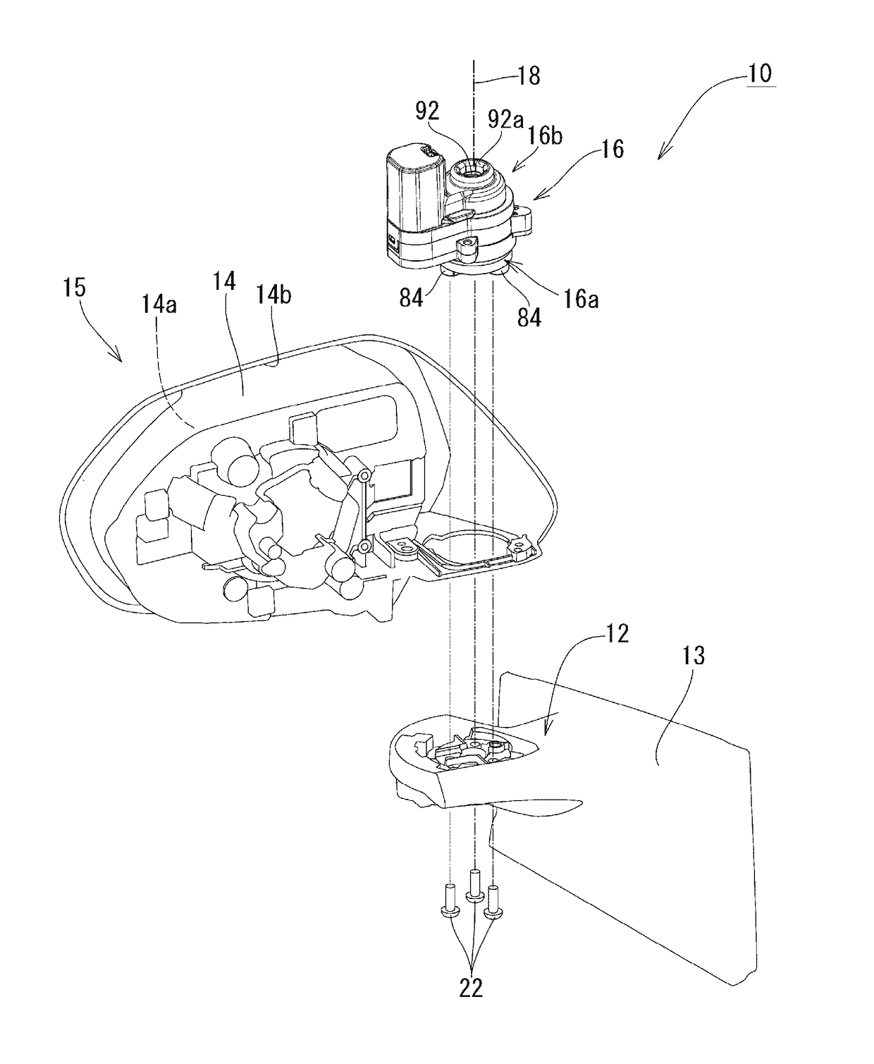
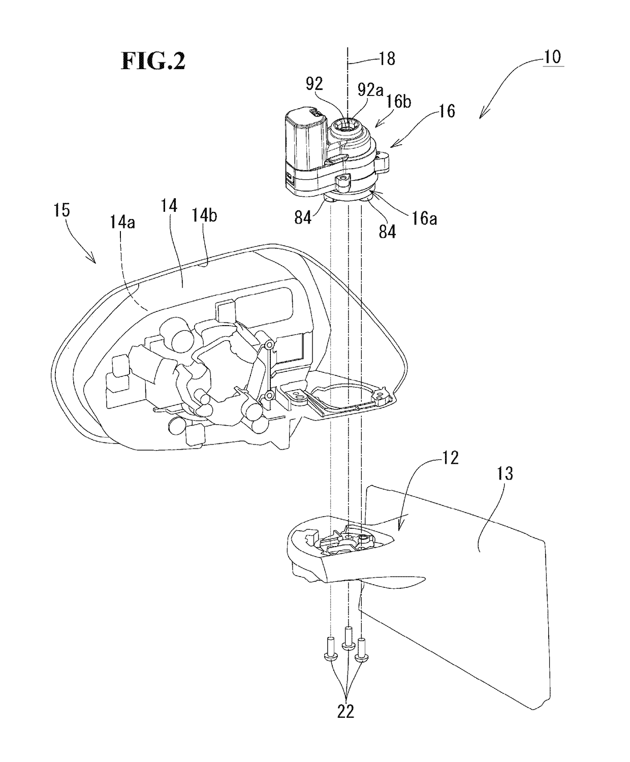
[0036]FIG. 2 is an exploded view of an electric retractable door mirror for a vehicle to which this invention is applied. FIG. 2 illustrates a state of a mirror rotating section 15 (view device rotating section) in an extended position as viewed from the back side (that is. the vehicle front side). Also, in FIG. 2, illustration of, e.g., a mirror surface adjustment actu...


PUM


Abstract

The electric retractable view device for a vehicle includes a view device rotating section including a view section body mounted therein, a rotation support section that supports the view device rotating section so as to be rotatable relative to a predetermined rotation axis, and an electric driving mechanism that electrically moves the view device rotating section to either of a retracted position and an extended position. The electric driving mechanism includes a motor, and a power transmission mechanism that transmits a drive force of the motor to the view device rotating section to rotate the view device rotating section in the direction around the rotation axis. The power transmission mechanism includes a double-threaded worm, and one or more motor-side worms disposed on the motor side relative to the double-threaded worm. Each of the one or more motor-side worms is a single-threaded worm.

Description

[0001]The disclosure of Japanese Patent Application No. JP2017-071003 filed on Mar. 31, 2017 including the specification, drawings, claims and abstract is incorporated herein by reference in its entirety.BACKGROUND OF THE INVENTION1. Field of the Invention[0002]This invention relates to an electric retractable view device for a vehicle. In the electric retractable view device of this invention, a double-threaded worm (double start worm) is used in a power transmission mechanism, reducing wear of gears and the like by taking some ingenuity in disposition of the double-threaded worm.2. Description of the Related Art[0003]As conventional electric retractable view devices for a vehicle in which a multiple-threaded worm (multiple start worm) is disposed in a power transmission system, there are electric retractable door mirrors described in Japanese Patent Laid-Open Nos. 2014-024387 and 2000-264130. The electric retractable door mirror described in Japanese Patent Laid-Open No. 2014-0243...

Claims


Application Information

Patent Timeline
Patent Type & Authority Applications(United States)
IPC IPC(8): B60R1/074F16H19/00F16H1/16
CPCB60R1/074F16H19/001F16H1/16B60R1/076F16H1/225
Inventor MOTOMIYA, MASAHIROICHIKAWA, KENJI
Owner MURAKAMI CORP
Why Eureka
Try Eureka