Light guide device and display apparatus

a technology of light guide device and display apparatus, which is applied in the direction of optical light guide, optics, instruments, etc., can solve the problems of reducing brightness and remarkably reducing the intensity of light beams reflected by a part of the plurality of partial reflection surfaces, and achieve the effect of increasing the intensity of each light beam and high brightness

Active Publication Date: 2018-10-04
SEIKO EPSON CORP
View PDF0 Cites 2 Cited by
  • Summary
  • Abstract
  • Description
  • Claims
  • Application Information

AI Technical Summary

Benefits of technology

[0007]In this configuration, when the light beams travel through the light guide portion from the one end side toward the another end side and are emitted from the partial reflection surfaces, the light beams reflected by the plurality of partial reflection surfaces are incident on an eye of an observer. At that time, an incident angle of the light beam, which is reflected by the partial reflection surface positioned on the one end side and is directed toward the eye, with respect to the partial reflection surface is larger than an incident angle of the light beam, which is reflected by the partial reflection surface positioned on the another end side and is directed toward the eye, with respect to the partial reflection surface. In this configuration, the appropriate incident angle range of the partial reflection surfaces positioned on the one end side is set to a larger angle than the appropriate incident angle range of the partial reflection surfaces positioned on the another end side. Therefore, it is possible to increase intensity of each light beam which is reflected by each of the plurality of partial reflection surfaces and is incident on the eye of the observer, and thus the observer can recognize an image with high brightness.

Problems solved by technology

As a result, in a case where an incident angle dependence on a reflectance of each of the plurality of partial reflection surfaces is the same, there is a problem that intensity of the light beams reflected by a part of the plurality of partial reflection surfaces is remarkably reduced and brightness is reduced.

Method used


Image

  • Light guide device and display apparatus
  • Light guide device and display apparatus
  • Light guide device and display apparatus

Examples


first embodiment

Overall Configuration

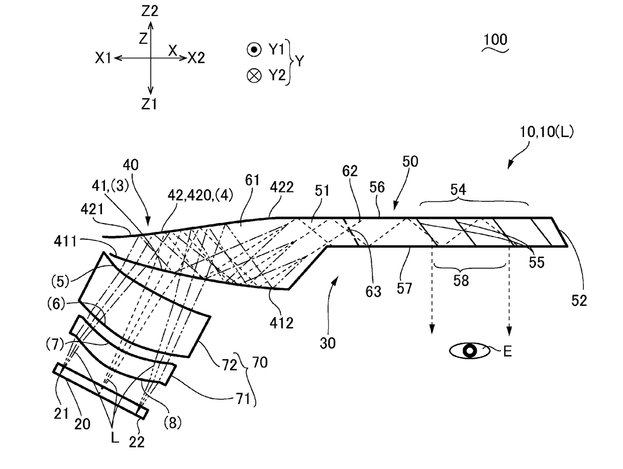
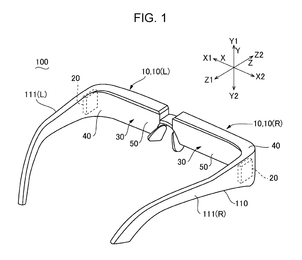
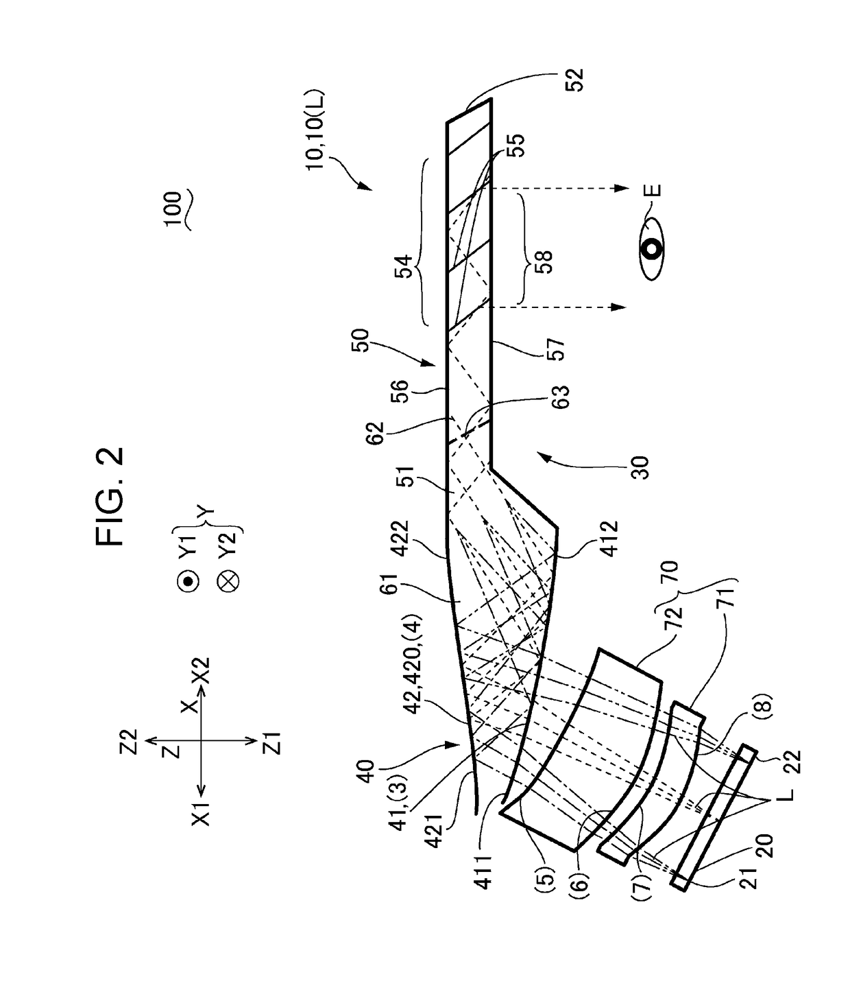
[0035]FIG. 1 is an explanatory view schematically illustrating an example of an appearance of a display apparatus 100 according to a first embodiment. The display apparatus 100 illustrated in FIG. 1 is configured with a see-through type eye glass display or the like, and includes a frame 110 provided with temples 111(R) and 111(L) on left and right sides thereof. In the display apparatus 100, a display unit 10 to be described is supported by the frame 110, and an image emitted from the display unit 10 is recognized by a user, as a virtual image. In the present embodiment, the display apparatus 100 includes a right-eye display unit 10(R) and a left-eye display unit 10(L) as the display unit 10. The right-eye display unit 10(R) and the left-eye display unit 10(L) have the same configuration, and are disposed symmetrically in a right-left direction. Thus, in the following description, the left-eye display unit 10(L) will be mainly described, and a description of th...

second embodiment

[0069]FIG. 15 is an explanatory diagram of the partial reflection surfaces 55 of the light guide system 30 according to a second embodiment, and illustrates a state when a light path of each light beam incident on the eye E is viewed from the eye E side. FIG. 16 is an explanatory diagram illustrating from which directions the light beams reflected by the plurality of partial reflection surfaces 55 illustrated in FIG. 15 are incident on the eye E. In an upper portion of FIG. 16, in a case where the eye E is positioned at the center, the left side, and the right side, a state where the light beams reflected by each of the partial reflection surfaces 55(1) to 55(16) are incident on the eye E from each angle direction in the first direction X, is illustrated. In a lower portion of FIG. 16, the results illustrated in the upper portion of FIG. 16 are superimposed. FIG. 17 is an explanatory diagram illustrating a state where the appropriate incident angle ranges are set by grouping the par...

third embodiment

[0077]FIG. 19 is an explanatory diagram of the partial reflection surfaces 55 of the light guide system 30 according to a third embodiment, and illustrates a state when a light path of each light beam incident on the eye E is viewed from the eye E side. FIG. 20 is an explanatory diagram illustrating which angle directions the light beams reflected by the partial reflection surfaces 55 illustrated in FIG. 19 are incident on the eye E. In an upper portion of FIG. 20, in a case where the eye E is positioned at the center, the left side, and the right side, a state where the light beams reflected by each of the partial reflection surfaces 55(1) to 55(6) are incident on the eye E from each angle direction in the first direction X, is illustrated. In a lower portion of FIG. 20, the results illustrated in the upper portion of FIG. 20 are superimposed. FIG. 21 is an explanatory diagram illustrating a manner in which the appropriate incident angle ranges are set by grouping the partial refle...


PUM


Abstract

A light guide device used in a display apparatus includes a transparent light guide portion that guides light beams incident from one end side to a light-emitting portion. The light guide portion includes a plurality of partial reflection surfaces between a first surface and a second surface which are parallel to each other, the plurality of partial reflection surfaces being inclined at the same angle from a normal direction with respect to the second surface toward the one end side. In the plurality of partial reflection surfaces, an appropriate incident angle range of the partial reflection surface positioned on the one end side is set to a larger angle than that of the partial reflection surface positioned on another end side.

Description

BACKGROUND1. Technical Field[0001]The present disclosure relates to a light guide device and a display apparatus.2. Related Art[0002]As a light guide portion of a light guide device used in a display apparatus or the like, a configuration in which a plurality of obliquely-inclined half mirrors are provided in parallel between two flat surfaces (a first surface and a second surface) extending from one end side on which image light beams are incident toward another end side, has been proposed (refer to JP-A-2016-177231). In the light guide device, the image light beams are reflected between the first surface and the second surface, travel through the light guide portion from one end side toward another end side, and are emitted from the half mirrors toward an eye of an observer. Thus, the observer can recognize a virtual image, and light beams from the outside can reach the eye of the observer via the light guide portion.[0003]JP-A-2017-3845 is an example of the related art.[0004]Howe...

Claims


Application Information

Patent Timeline
Patent Type & Authority Applications(United States)
IPC IPC(8): G02B27/01F21V8/00
CPCG02B27/0172G02B6/002G02B6/003G02B2027/0178G02B2027/0118G02B2027/0145G02B2027/0125
Inventor MATSUKI, HAYATOTAKEDA, TAKASHI
Owner SEIKO EPSON CORP
Why Eureka
Try Eureka