
Method for generating settings for machining an optical lens

a technology for machining and optical lenses, applied in the field of eyeglasses, can solve the problems of long operation of input information, inability to use the above-mentioned communication protocol, and inability to optimize software to reduce the duration of the machining cycle of the lens, and achieve the effect of reducing the duration of the machining cycl

Active Publication Date: 2018-10-04
ESSILOR INT CIE GEN DOPTIQUE
View PDF5 Cites 1 Cited by
  • Summary
  • Abstract
  • Description
  • Claims
  • Application Information

AI Technical Summary

Benefits of technology

The patent text discusses a method for machining optical lenses by dividing the shape into "objects" and treating each object separately. This allows for the use of different tools and settings for each object, ultimately reducing the time and number of tool changes required for the entire machining process. The technical effect is improved efficiency and productivity in the optical lens manufacturing process.

Problems solved by technology

Thus, the aforementioned communication protocol cannot be used.
One drawback is that this software is generally not optimized to decrease the duration of the machining cycle of the lens.
Another drawback is that the operation of inputting information is long and tedious for the optician to implement.
The problem with these machining settings is that not only are they not standard (they are generated depending on the characteristics of the machining machine and on the prescriptions of the wearer, and hence they are specific to this machine and to the wearer), but they are furthermore static (they cannot be adjusted when the characteristics of the machining machine change or when the prescriptions of the wearer change).
As soon as a machining tool is replaced by another more effective tool of different shape, all of the stored machining settings become unusable.

Method used


Image

  • Method for generating settings for machining an optical lens
  • Method for generating settings for machining an optical lens
  • Method for generating settings for machining an optical lens

Examples


Embodiment Construction

[0042]The description which follows with reference to the appended drawings, which are given by way of nonlimiting examples, will make it easy to understand what the invention consists of and how it may be achieved.

[0043]In the appended drawings:

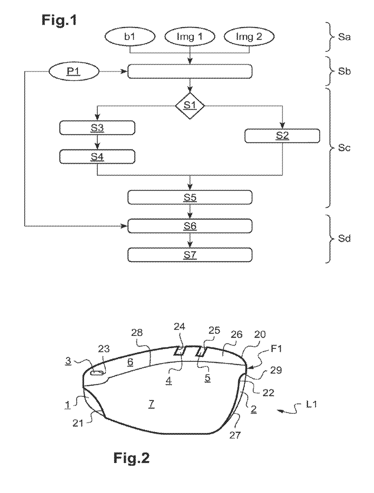
[0044]FIG. 1 is a flowchart illustrating the steps of an algorithm allowing a method for generating settings for machining an optical lens according to the invention to be implemented;

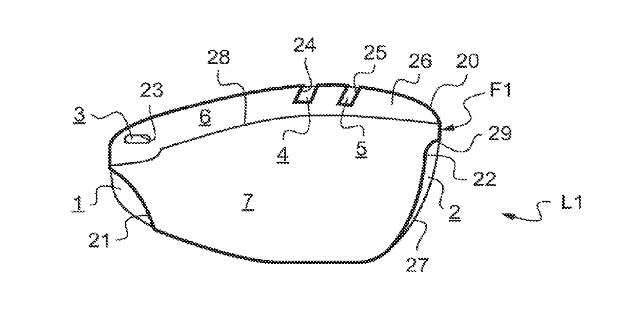
[0045]FIG. 2 is a schematic view of the outline of an optical lens, in which various objects characterizing the shape of this outline are shown;

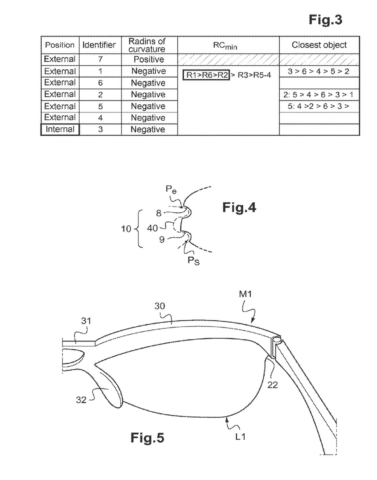
[0046]FIG. 3 is a table illustrating a method for sequencing the machining of the objects of FIG. 2;

[0047]FIG. 4 is a schematic view of a portion of an optical lens; and

[0048]FIG. 5 is a schematic perspective view of a portion of a spectacle frame equipped with the optical lens of FIG. 2.

[0049]As FIG. 5 shows, a pair of spectacles generally includes a spectacle frame M1 and two optical lenses L1 (a single one of which i...


PUM


Abstract

Disclosed is a method for generating settings for machining an optical lens, including: a) acquiring a file characterizing the shape to which the optical lens must be machined in order to allow it to be mounted in a spectacle frame; b) decomposing the shape into a plurality of distinct objects, including an exterior envelope inside of which all the other objects are located; c) determining a machining order of the other objects; and d) generating the machining settings depending on the machining order.

Description

TECHNICAL FIELD OF THE INVENTION[0001]The present invention generally relates to the field of eyeglasses.[0002]It more particularly relates to a method for generating settings for machining an optical lens, with a view to mounting it in a spectacle frame.[0003]The invention has a particularly advantageous application in the machining of optical lenses of complex shapes, i.e. in the machining of lenses not able to be machined by means of one and the same tool.TECHNOLOGICAL BACKGROUND[0004]The technical part of an optician's job consists in mounting a pair of optical lenses in a spectacle frame selected by a wearer.[0005]This mounting operation includes a first step of acquiring the geometry of the rims of the selected spectacle frame, and a second step of machining the lens, which in particular comprises an operation in which the outline of the lens is edged to the desired shape.[0006]This edging operation consists in removing the superfluous peripheral portion of the optical lens in...

Claims


Application Information

Patent Timeline
IPC IPC(8): G05B19/4093B24B13/005B24B9/14
CPCG05B19/40938B24B13/0052B24B9/148G05B2219/36268G05B2219/36296B24B13/00Y02P90/02
Inventor ANATOLE, VINCENTSILEO, CEDRIC
Owner ESSILOR INT CIE GEN DOPTIQUE
Learn More