Manufacturing method of reactor and heating device

a manufacturing method and heating device technology, applied in the manufacture of magnetic cores, transformers/inductance details, electrical devices, etc., can solve the problems of not being able to avoid heat being produced in the winding of reactor coils, and achieve the effects of increasing the density of magnetic flux, reducing the loss of heating cores, and increasing the heat production

Active Publication Date: 2018-10-04
TOYOTA JIDOSHA KK
View PDF3 Cites 4 Cited by
  • Summary
  • Abstract
  • Description
  • Claims
  • Application Information

AI Technical Summary

Benefits of technology

[0007]An area of a bonding interface between the first core segment and the second core segment may be smaller than each of an area of a region of the heating core that faces the first core segment and an area of a region of the heating core that faces the second core segment. The smaller the area through which the magnetic flux passes, the higher the density of the magnetic flux, which means a larger amount of heat produced per unit area. When the regions of the heating core that face the core segments are large, the temperatures of the core segments in the vicinity of the boundary between the heating core and the core segments rise slowly, and meanwhile the temperatures of the core segments in the vicinity of a bonding portion therebetween can be raised quickly.
[0008]A frequency of the alternating current may be a frequency such that a loss in the heating core is smaller than a loss in each of the first core segment and the second core segment; and as the alternating current of the frequency flows through the heating coil, the loss of the heating core due to magnetic hysteresis and an eddy current may occur in the first core segment and the second core segment. When an alternating current is applied to the heating coil, a loss (iron loss) due to magnetic hysteresis and an eddy current occurs in the first core segment and the second core segment. The amount of heat produced per unit area of the core is attributable to a loss in the core. The unit area here means a unit area orthogonal to a magnetic flux passing through. The loss in the core depends on the material of the core and the frequency of the current applied. Selecting such a material of the heating core and such a frequency of the alternating current that the loss in the heating core becomes relatively small can reduce the loss in the heating core, so that the magnetic energy can be effectively used to produce heat in the core segments.
[0009]One end of the heating core may be disposed adjacent to a bonding portion between the first core segment and the second core segment; and the other end of the heating core may be disposed adjacent to the bonding portion between the first core segment and the second core segment. This configuration can reduce the length of the closed magnetic circuit including the bonding portion (thermosetting adhesive) and increase the amount of heat produced in the vicinity of the bonding portion. As a result, the thermosetting adhesive can be heated more effectively.
[0010]A bonding portion between the first core segment and the second core segment may be located inside the reactor coil. When the bonding portion is located inside the reactor coil, a heater cannot heat the bonding portion without also heating the reactor coil. Thus, the temperature of the reactor coil rises. The technique of JP 2014-33039 A cannot avoid heat being produced in the reactor coil as a magnetic flux passes through the winding of the reactor coil and an eddy current occurs. Thus, the temperature of the reactor coil rises. By contrast, the reactor manufacturing method disclosed by the present specification passes a magnetic flux to the bonding portion through the core segments of the reactor, so that most of the magnetic flux does not pass through the winding of the reactor coil. Therefore, the reactor manufacturing method disclosed by the present specification can efficiently heat the bonding portion (thermosetting adhesive), even when it is located inside the reactor coil, while suppressing the temperature rise of the reactor coil.

Problems solved by technology

Thus, the technique of JP 2014-33039 A cannot avoid heat being produced in the winding of reactor coil due to the magnetic flux passing therethrough.

Method used


Image

  • Manufacturing method of reactor and heating device
  • Manufacturing method of reactor and heating device
  • Manufacturing method of reactor and heating device

Examples


Embodiment Construction

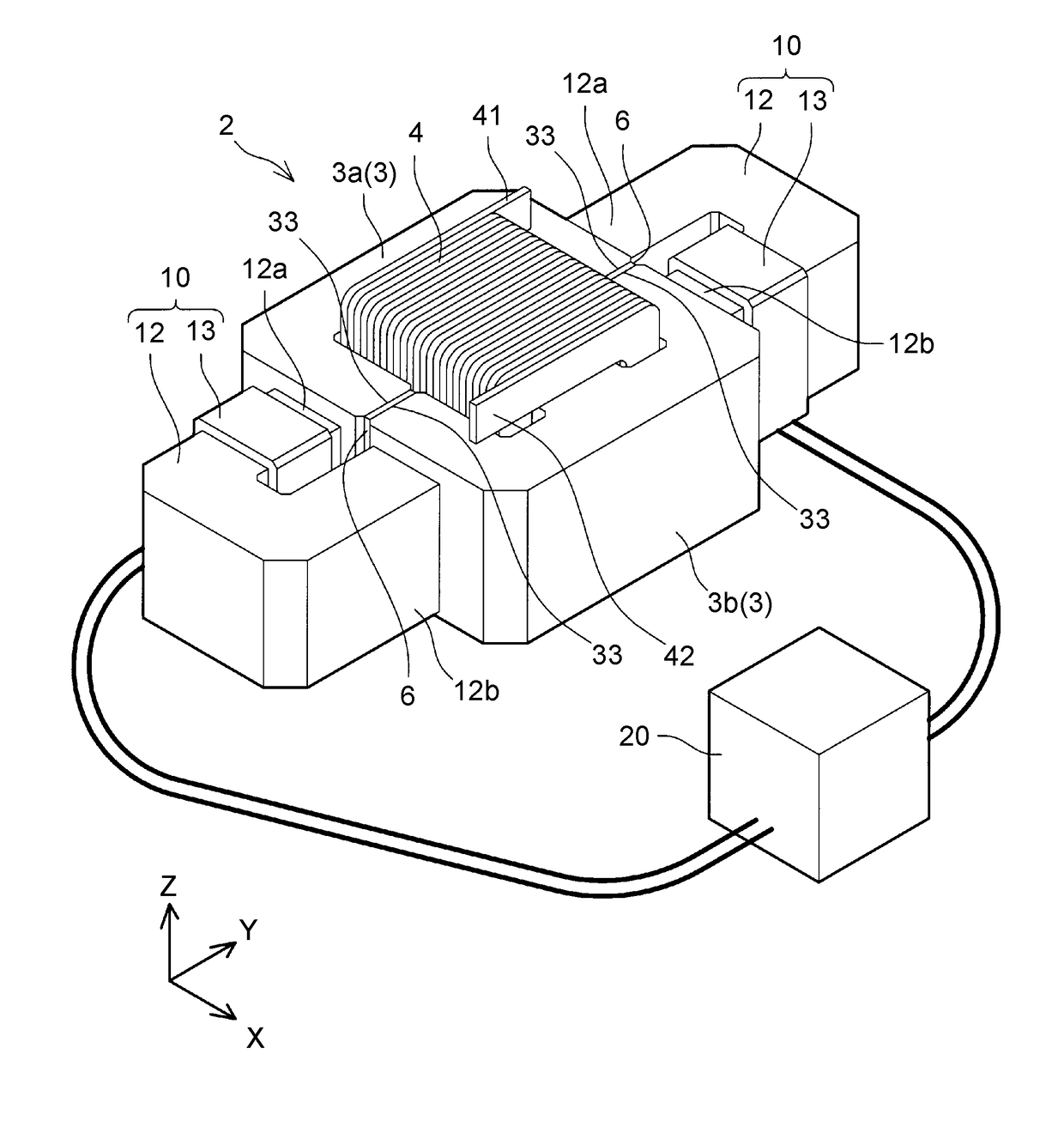
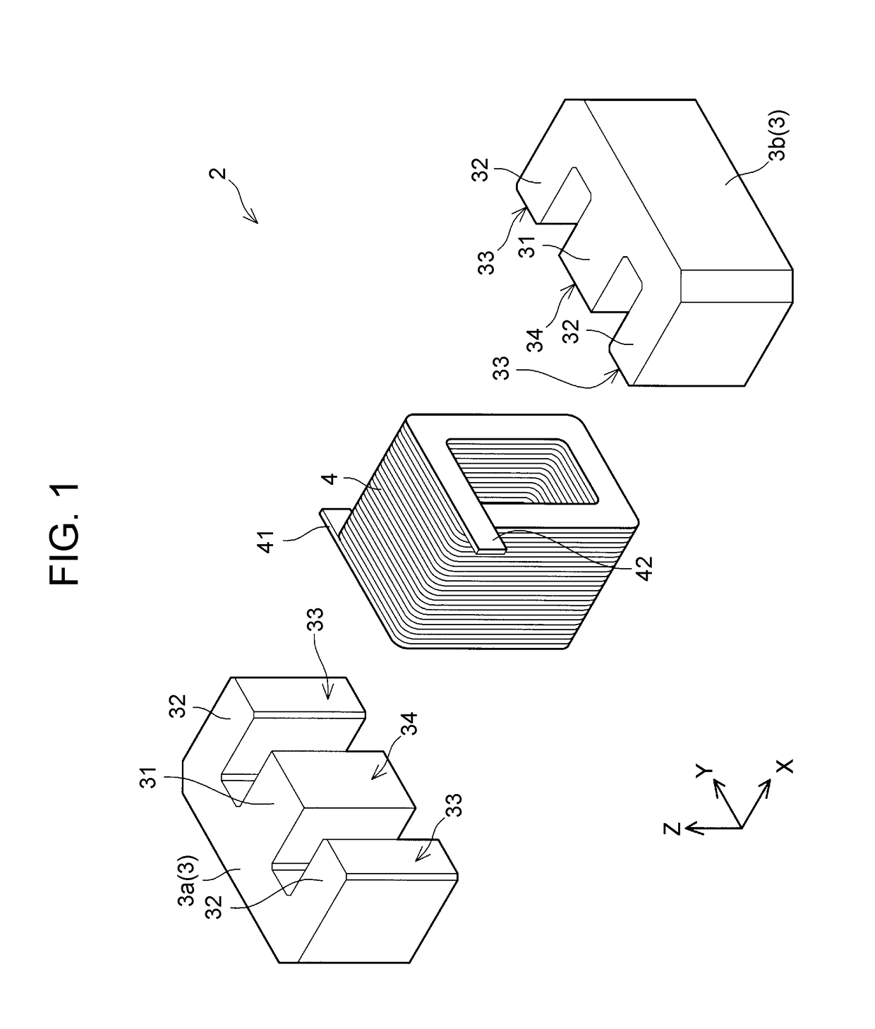
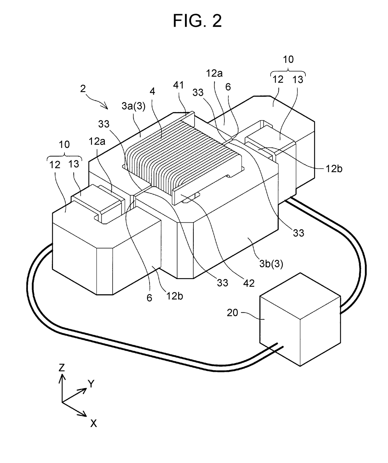
[0023]A reactor manufacturing method of an embodiment will be described with reference to the drawings. First, a reactor 2 that is one example of the reactor manufactured by the manufacturing method of the embodiment will be described. FIG. 1 is an exploded perspective view of the reactor 2. The reactor 2 includes two E-shaped core segments 3a, 3b, and a coil 4. The core segments 3a, 3b will be collectively referred to as a reactor core 3. The two core segments 3a, 3b have the same shape. The core segments 3a, 3b are disposed so that leading end surfaces 33, 34 of three straight parts 32, 31 extending parallel to one another of one core segment face those of the other core segment, with the central straight parts 31 passed through an inside of the coil 4.

[0024]The leading end surfaces 33 of the right and left straight parts 32 of the core segment 3a are bonded with those of the core segment 3b. In other words, the leading end surfaces 33 constitute bonding interfaces between the two...


PUM

PropertyMeasurementUnit
alternating magnetic fluxaaaaaaaaaa
temperatureaaaaaaaaaa
areaaaaaaaaaaa

Abstract

A manufacturing method of a reactor includes: mounting a reactor coil onto a first core segment and a second core segment, and placing the first core segment and the second core segment face to face, with an uncured thermosetting adhesive sandwiched between the first core segment and the second core segment; placing a heating core such that one end of the heating core is wound faces the first core segment, and the other end of the heating core faces the second core segment; producing heat in the first core segment and the second core segment by an alternating magnetic flux; and binding together the first core segment and the second core segment by a temperature rise and cure of the thermosetting adhesive.

Description

INCORPORATION BY REFERENCE[0001]The disclosure of Japanese Patent Application No. 2017-063768 filed on Mar. 28, 2017 including the specification, drawings and abstract is incorporated herein by reference in its entirety.BACKGROUND1. Technical Field[0002]A technology to be disclosed by the present specification relates to a reactor manufacturing method and a heating device that is used in manufacturing reactors.2. Description of Related Art[0003]A reactor of which a core, around which a coil is wound, is divided into a plurality of core segments is known. Such core segments are sometimes bonded together with a thermosetting adhesive. For example, Japanese Patent Application Publication No. 2007-335523 (JP 2007-335523 A) and Japanese Patent Application Publication No. 2014-33039 (JP 2014-33039 A) disclose a technique relating to the bonding of core segments using a thermosetting adhesive. The technique of JP 2007-335523 A involves the following steps: A coil is mounted onto two core s...

Claims


Application Information

Patent Timeline
Patent Type & Authority Applications(United States)
IPC IPC(8): H01F41/02B29C65/04B29C65/48
CPCH01F41/02B29C65/04B29C65/4835H01F27/263H01F41/0206H01F27/306
Inventor TANAHASHI, FUMIKI
Owner TOYOTA JIDOSHA KK
Why Eureka
Try Eureka