Reciprocating power generating module

Inactive Publication Date: 2009-06-11
IND TECH RES INST
View PDF10 Cites 32 Cited by
  • Summary
  • Abstract
  • Description
  • Claims
  • Application Information

AI Technical Summary

Benefits of technology

[0006]The object of the present invention is to provide a reciprocating power generating module, capable of achieving high magnetic flux density uti

Problems solved by technology

Reciprocating dynamo flashlights have been available on the market for a conceivable period of time, but for its lack of adequate power generating efficiency, it had been determined to be impractical in usage.
Among which, the reciprocating type is the least used even when the linear reciprocating motion is the most direct form of power transmission in many applications since it usually requires to be converted into a rotation motion through a certain mechanism and thus causes the whole system to have poor performance.
In addition, the power generating efficiency of those c

Method used


Image

  • Reciprocating power generating module
  • Reciprocating power generating module
  • Reciprocating power generating module

Examples


Example

[0013]For your esteemed members of reviewing committee to further understand and recognize the fulfilled functions and structural characteristics of the invention, several exemplary embodiments cooperating with detailed description are presented as the follows.

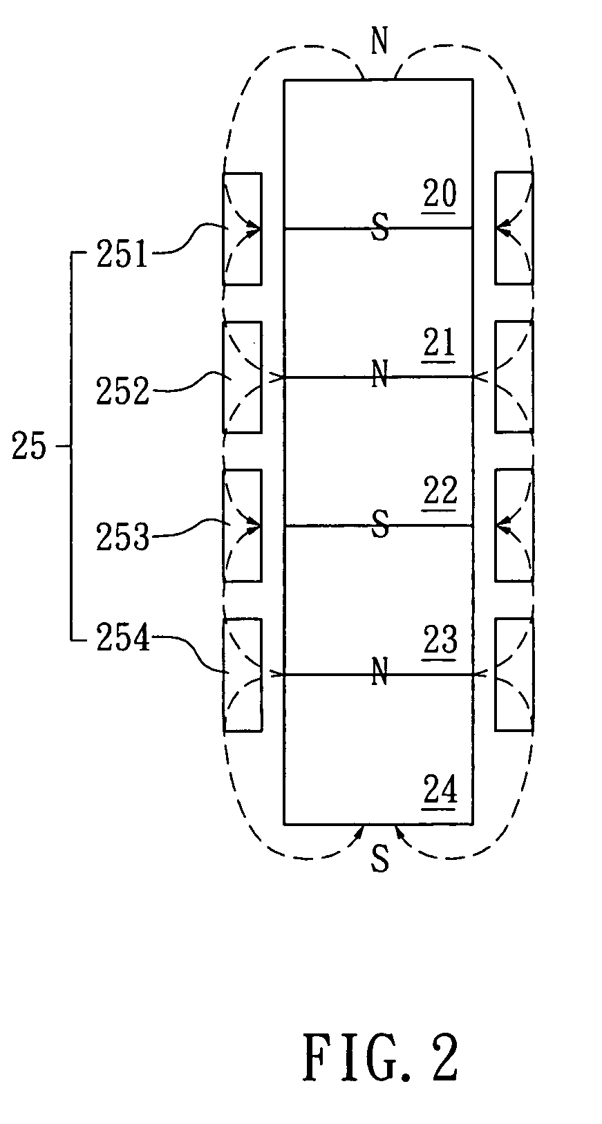
[0014]Please refer to FIG. 2, which is a schematic diagram illustrating the power generating principle of a reciprocating power generating module of the invention. In the reciprocating power generating module of FIG. 2, there are five anisotropic magnets 20, 21, 22, 23, 24 being connected with each other in a manner that poles of any one of the five magnets are orientated to repel poles of its neighboring magnets, i.e. the North pole of a magnet is disposed facing to the North pole of its neighboring magnet while enabling the South pole of its another neighboring magnet to be orientated to the South pole thereof. Moreover, a coil 25 is wound around the exterior of the concatenating magnets 20, 21, 22, 23, 24 in a series of alt...


PUM


Abstract

A reciprocating power generating module is disclosed, which comprises: a guide; a magnet, being an integrated unit composed of at least two magnetic elements connected with each other in a manner that poles of any one of the plural magnetic elements are orientated to repel poles of its neighboring magnetic elements; and a coil, being wound around the guide; wherein the magnet is capable of being driven to move linearly by the defining of the guide. The full sine-wave AC voltage output is obtained when the relative linear motion equals double of the length of the magnetic element.

Description

FIELD OF THE INVENTION[0001]The present invention relates to a reciprocating power generation module, and more particularly, to a reciprocating power generation module, being an integrated unit composed of a plurality of magnets and a multi-cell coil in a manner that the plural magnets are connected with each other for orientating poles of any one of the plural magnets to repel poles of its neighboring magnets.BACKGROUND OF THE INVENTION[0002]Electrical generators will find a wide application in all fields of technology. Following the call for less use of batteries, the development for having a compact and highly efficient electrical generator is in high demand. Generally, the compact-sized electrical generator is used as the power supply for portable electronic devices. However, for the proliferation of compact portable electrical generators, it is crucial that those compact portable electrical generators should be able to generate electricity with sufficient capacity in a limited ...

Claims


Application Information

Patent Timeline
IPC IPC(8): H02K35/00
CPCH02K35/02H02K7/1876
Inventor PENG, WEN-YANGCHIANG, CHUNG-PINGLO, CHAN-HSING
Owner IND TECH RES INST
Why Eureka
Try Eureka