
Audio decoding apparatus and method for band expansion with aliasing suppression

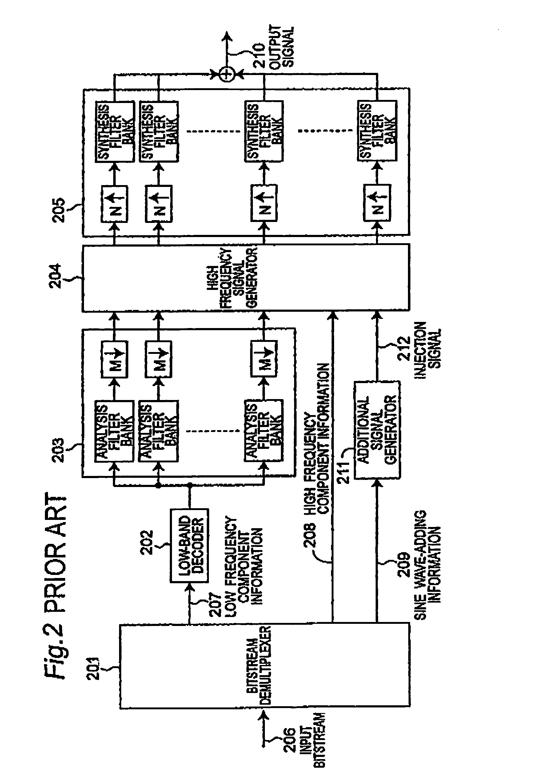
a bandwidth expansion and decoding apparatus technology, applied in the field of decoding apparatus and decoding methods for an audio bandwidth expansion system, can solve the problems of reducing the number of calculations, increasing power consumption, and reducing the playback time that is possible with a given power supply capacity, and achieves low bitrate and high quality audio playback

Inactive Publication Date: 2006-06-06
PANASONIC CORP +1
View PDF15 Cites 74 Cited by
  • Summary
  • Abstract
  • Description
  • Claims
  • Application Information

AI Technical Summary

Benefits of technology

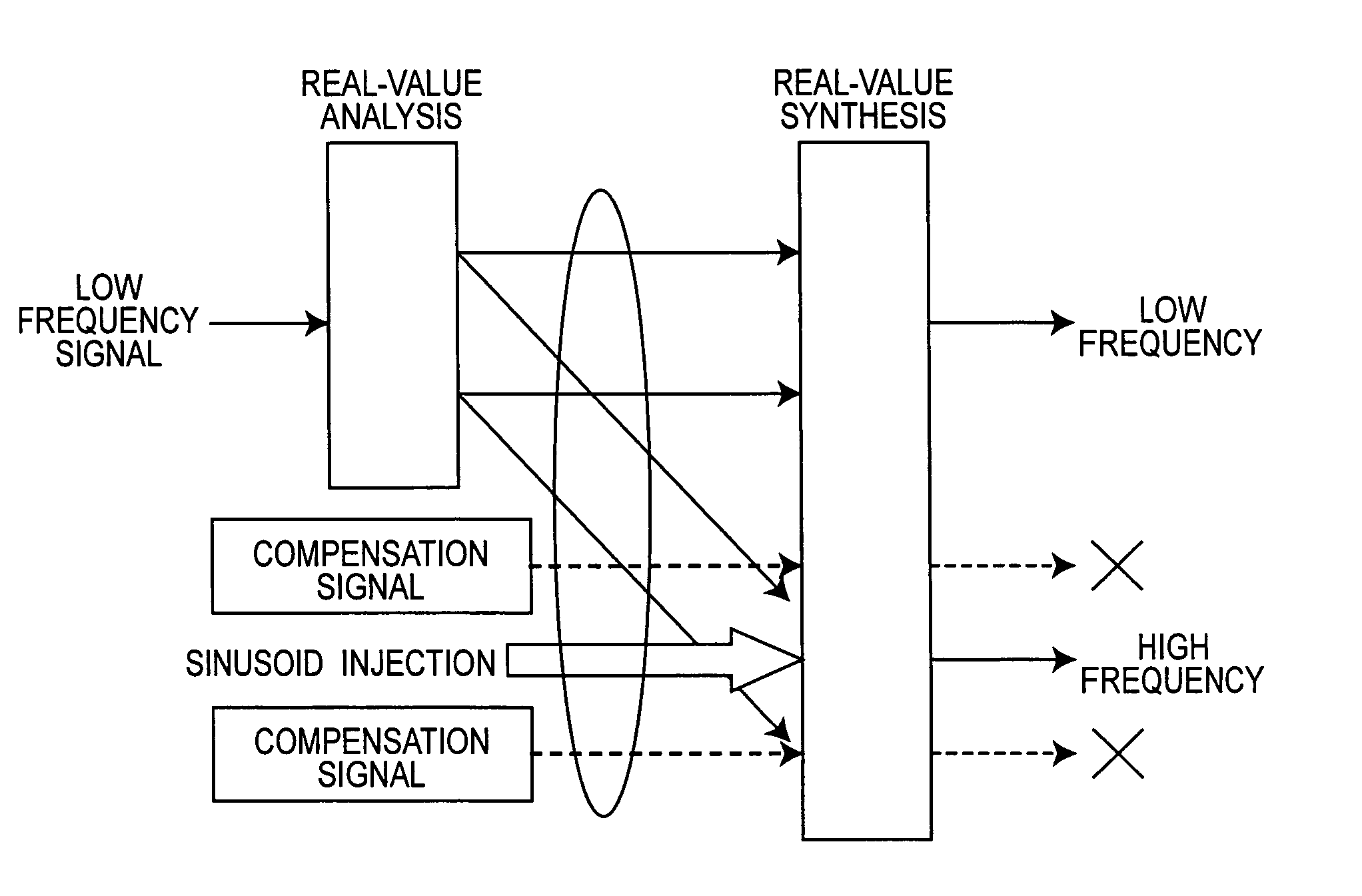
The present invention provides an audio decoding apparatus that can decimate an audio signal from a bitstream containing encoded information about a narrowband audio signal and additional information for expanding the narrowband signal to a wideband signal. The additional information contains high frequency component information and sinusoid-adding information. The apparatus includes a bitstream demultiplexer, a decoding means, an analysis subband filter, a high frequency signal generator, a sinusoidal signal addition means, a compensation signal generator, and a real-valued calculation synthesis subband filter. This invention allows for high quality audio playback at a low bitrate using few calculations.

Problems solved by technology

A problem when the decoder is built for LSI devices, for example, is that power consumption increases and the playback time that is possible with a given power supply capacity decreases.
While this reduces the number of calculations, if a sine wave is added using the same method as when the synthesis filter bank performs complex-valued calculations, a pure sine wave is not actually added and the intended result is not achieved in the reproduced audio.

Method used


Image

  • Audio decoding apparatus and method for band expansion with aliasing suppression
  • Audio decoding apparatus and method for band expansion with aliasing suppression
  • Audio decoding apparatus and method for band expansion with aliasing suppression

Examples


embodiment 1

(Embodiment 1)

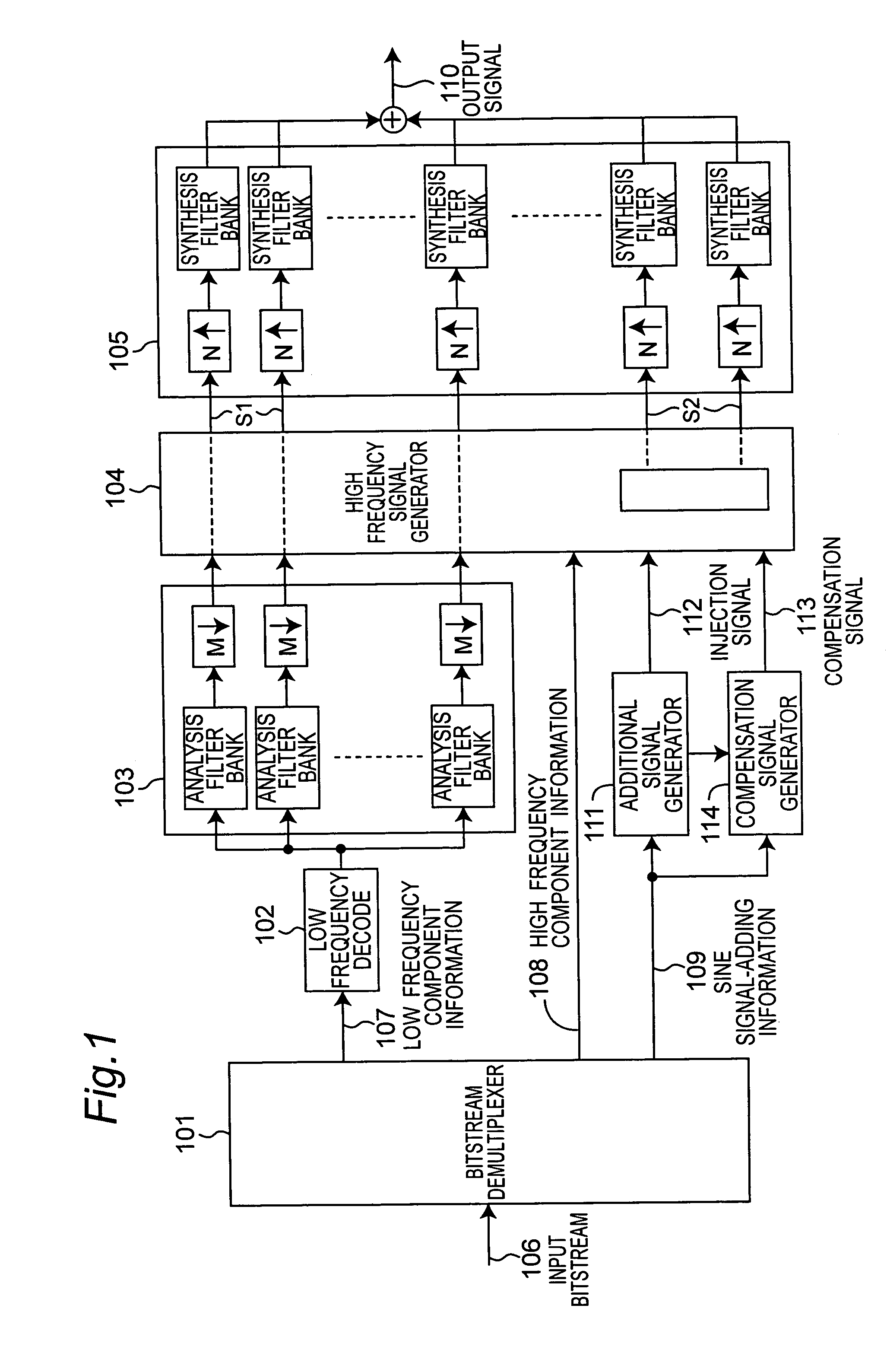
[0041]FIG. 1 is a schematic diagram showing a decoding apparatus performing bandwidth expansion by means of spectral band replication (SBR) based on a first embodiment of the present invention.

[0042]The input bitstream 106 is demultiplexed by the bitstream demultiplexer 101 into low frequency component information 107, high frequency component information 108, and sine signal-adding information 109. The low frequency component information 107 is information that is encoded using, for example, the MPEG-4 AAC coding method, is decoded by the low frequency decoder 102, and a time signal representing the low frequency component is generated. The resulting time signal representing the low frequency component is then divided into multiple (M) subbands by the analysis filter bank 103, and input to the bandwidth expansion means (high frequency signal generator) 104. The high frequency signal generator 104 copies the low frequency subband signal representing the low frequency c...

embodiment 2

(Embodiment 2)

[0075]FIG. 12 is a schematic diagram showing an additional signal generator in a second embodiment of the present invention. This additional signal generator differs from the additional signal generator, 111 shown in FIG. 4 in that interpolated information 1201 calculated by the sinusoid generating means 405 is input to compensation signal generator 410 so that the compensation signal 113 is calculated based on the interpolated information 1201.

[0076]The sinusoid generating means 405 in the above first embodiment adjusts the amplitude of the generated sine wave based only on the amplitude information of the current frame extracted by the amplitude extraction means 403. The sinusoid generating means 405 of this second embodiment, however, interpolates the amplitude information using amplitude information from neighboring frames, and adjusts the amplitude of the generated sine wave based on this interpolated amplitude information.

[0077]Because the amplitude of the genera...


PUM


Abstract

A wideband, high quality audio signal is decoded with few calculations at a low bitrate. Unwanted spectrum components accompanying sinusoidal signal injection by a synthesis subband filter built with real-value operations are suppressed by inserting a suppression signal to subbands adjacent to the subband to which the sine wave is injected. This makes it possible to inject a desired sinusoid with few calculations.

Description

TECHNICAL FIELD[0001]The present invention relates to a decoding apparatus and decoding method for an audio bandwidth expansion system for generating a wideband audio signal from a narrowband audio signal by adding additional information containing little information, and relates to technology enabling this system to provide high audio quality playback with few calculations.BACKGROUND ART[0002]Many audio encoding technologies for encoding an audio signal to a small data size and then reproducing the audio signal from the coded bitstream are known. The international ISO / IEC 13818-7 (MPEG-2 AAC) standard in particular is known as a superior method enabling high audio quality playback with a small code size. This AAC coding method is also used in the more recent ISO / IEC 14496-3 (MPEG-4 Audio) system.[0003]Audio coding methods such as AAC convert a discrete audio signal from the time domain to a signal in the frequency domain by sampling the time-domain signal at specific time intervals...

Claims


Application Information

Patent Timeline
Patent Type & Authority Patents(United States)
IPC IPC(8): G10L21/02G10L19/00G10L19/02G10L19/03G10L19/093H03M7/30
CPCG10L21/038G10L19/02
Inventor TSUSHIMA, MINEOTANAKA, NAOYANORIMATSU, TAKESHICHONG, KOK SENGKUAH, KIM HANNNEO, SUA HONGNOMURA, TOSHIYUKISHIMADA, OSAMUTAKAMIZAWA, YUICHIROSERIZAWA, MASAHIRO
Owner PANASONIC CORP
Learn More