Instant start electronic ballast with universal AC input voltage

a technology of electronic ballast and input voltage, which is applied in the direction of electric variable regulation, process and machine control, instruments, etc., can solve the problems of circuit instability, power factor correction circuits in prior art ballast circuits that can have difficulty in properly operating over the wide or universal ac input voltage range, and improve the efficiency of the unit, limit power losses, and improve the operation of power factor correction circuits

Inactive Publication Date: 2006-06-13
TECHN CONSUMER PRODS
View PDF15 Cites 74 Cited by
  • Summary
  • Abstract
  • Description
  • Claims
  • Application Information

AI Technical Summary

Benefits of technology

[0020]The present invention describes an electronic ballast that energizes fluorescent lamps in a parallel configuration. The ballast employs a power factor correcting boost converter that can be used over a wide range of AC line voltages to provide regulated power to a self-oscillating sine wave inverter that drives the fluorescent lighting load at high frequencies. The inverter employs several novel specialized networks that limit a certain type of shoot-through

Problems solved by technology

However, after ignition the lamp impedance changes to a low value.
This lowering of the lamp impedance with current, known as negative resistance, can cause circuit instability unless an impedance known as the ballast impedance is placed in series with the lamp load.
Power factor correction circuits in prior art ballast circuits can have difficulty in properly operating over the wide or universal AC input voltage range.
A cause of heating of the transistor switches in this type of inverter is

Method used


Image

  • Instant start electronic ballast with universal AC input voltage
  • Instant start electronic ballast with universal AC input voltage
  • Instant start electronic ballast with universal AC input voltage

Examples


Embodiment Construction

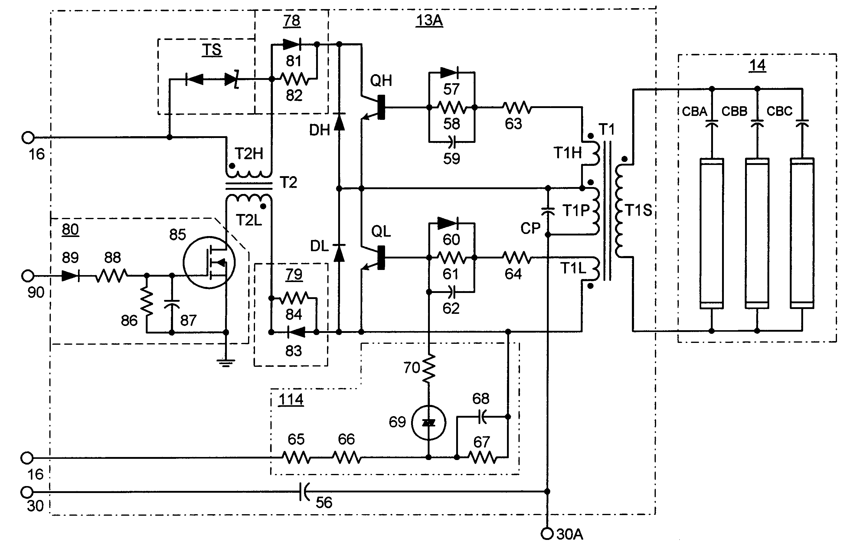
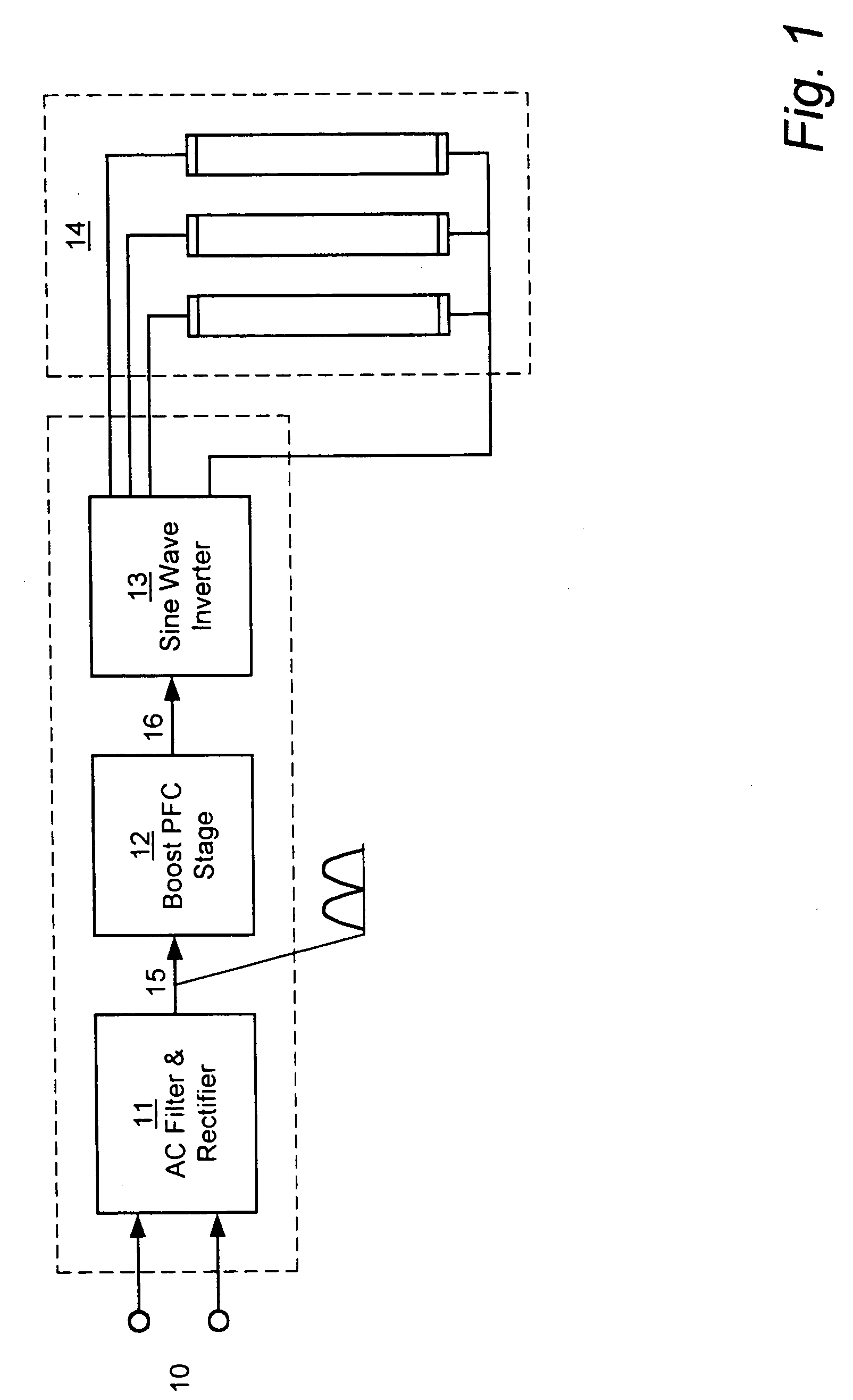
[0035]Generally speaking, the present invention is an electronic ballast that energizes lamps in a parallel configuration. The ballast employs a power factor correcting boost converter that can be used over a wide range of AC line voltages to provide regulated power to a self-oscillating sine wave inverter that drives the fluorescent lighting load at high frequencies. The inverter employs several novel specialized networks that limit a certain type of shoot-through current, and thus improve the efficiency of the unit. Also included is a restart circuit that limits power losses during the zero lamp condition, by periodically interrupting the inverter operation when the zero lamp state is detected. To improve the operation of the power factor correcting circuitry over the wide range of AC line voltages, a DC offset is added to the sampled AC voltage at the higher AC line voltages by a Zener diode based coupling circuit.

[0036]Referring first to FIG. 1, there is shown a block diagram th...


PUM


Abstract

The present invention relates to an electronic ballast that energizes fluorescent lamps connected in a parallel configuration. The ballast employs a power factor correcting boost converter that can be used over a wide range of AC line voltages to provide regulated power to a self-oscillating sine wave inverter that drives the fluorescent lighting load at high frequencies. The inverter employs special networks that limit a certain type of shoot-through current, and thus improve the efficiency of the unit. Also included is a restart circuit that limits power losses during the zero lamp condition, by periodically interrupting the inverter operation when the zero lamp state is detected. To improve operation of the power factor correcting circuitry over the wide range of AC line voltages, a DC offset is added to the sampled AC voltage at the higher AC line voltages by Zener diode based coupling circuit.

Description

REFERENCE TO PREVIOUSLY FILED APPLICATIONS[0001]This patent application is a continuation of and claims priority from U.S. Provisional Patent Application No. 60 / 368,857 filed on Mar. 29, 2002.FIELD OF THE INVENTION[0002]The present invention relates primarily to electronic ballasts, and more particularly to energy efficient instant start electronic ballasts that operate over a wide range of AC input voltages.BACKGROUND OF THE INVENTION[0003]With the increased interest in energy conservation, lighting systems that use less energy and are easy and cost-effective to install are becoming more important. This conclusion is apparent when one considers that lighting uses about 30% of the energy consumed in the United States. An effective method of reducing energy consumption that has been found by the lighting industry is to employ electronic ballasts that energize the lamps with high frequency alternating currents, operating at frequencies in the 20 kHz to 100 kHz range. Electrical energy...

Claims


Application Information

Patent Timeline
IPC IPC(8): G05F1/00H05B1/02
CPCH05B41/28H05B41/2821Y02B20/185Y02B20/00
Inventor KATYL, ROBERT H.DRANCHAK, DAVID W.
Owner TECHN CONSUMER PRODS
Why Eureka
Try Eureka