Switching power supply unit

a power supply unit and power supply technology, applied in the direction of electric variable regulation, process and machine control, instruments, etc., can solve the problems of reducing efficiency, affecting the surrounding electronic devices, and generating burst noise, so as to reduce power loss, improve unit efficiency, and reduce output voltage ripple

Inactive Publication Date: 2005-09-27
ROHM CO LTD
View PDF11 Cites 8 Cited by
  • Summary
  • Abstract
  • Description
  • Claims
  • Application Information

AI Technical Summary

Benefits of technology

[0011]It is, therefore, an object of the invention to provide an improved switching power supply unit capable of holding the switching frequency substantially constant at a low frequency to prevent the switching frequency from discontinuously changing and to suppress ripples in the output voltage when the load is light, thereby resulting in only a limited power loss for the light load.
[0024]With a switching power supply unit of the invention, the switching frequency of the unit is held substantially constant at a low frequency when the load is light, thereby reducing the power loss and improving the efficiency of the unit during a light-load period. In addition, burst noise substantially disappear, and hence ripple of the output voltage, may be reduced negligibly small as compared with conventional ones.

Problems solved by technology

The lowering of the efficiency is mainly due to the power loss accompanying the switching operation of the power supply unit.
However, under a burst-mode control, burst noises are generated in such conventional switching power supply unit as the unit undergoes a transition from an on-off period to an off-period due to the fact that the switching frequency changes discontinuously in the transition.
The burst noise gives adverse effects to the surrounding electronic devices, and can result in mutual interference among them.
A switching power supply unit also results in bursts of output power in a skip-mode control because on-off switching is performed only when the output voltage is raised from the lower limit to the upper limit.
Besides, large ripples result in the varying output voltage.
Such large ripples in the output voltage are unfavorable for the load.

Method used


Image

  • Switching power supply unit
  • Switching power supply unit
  • Switching power supply unit

Examples


Embodiment Construction

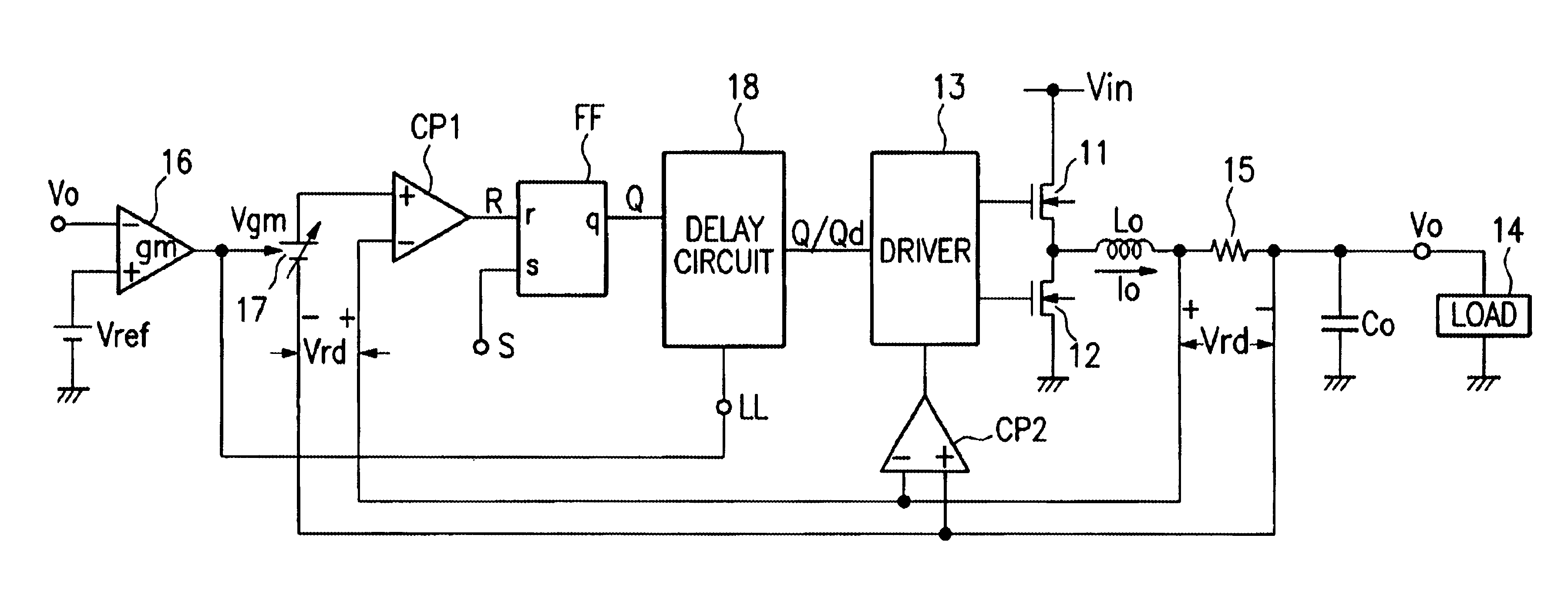
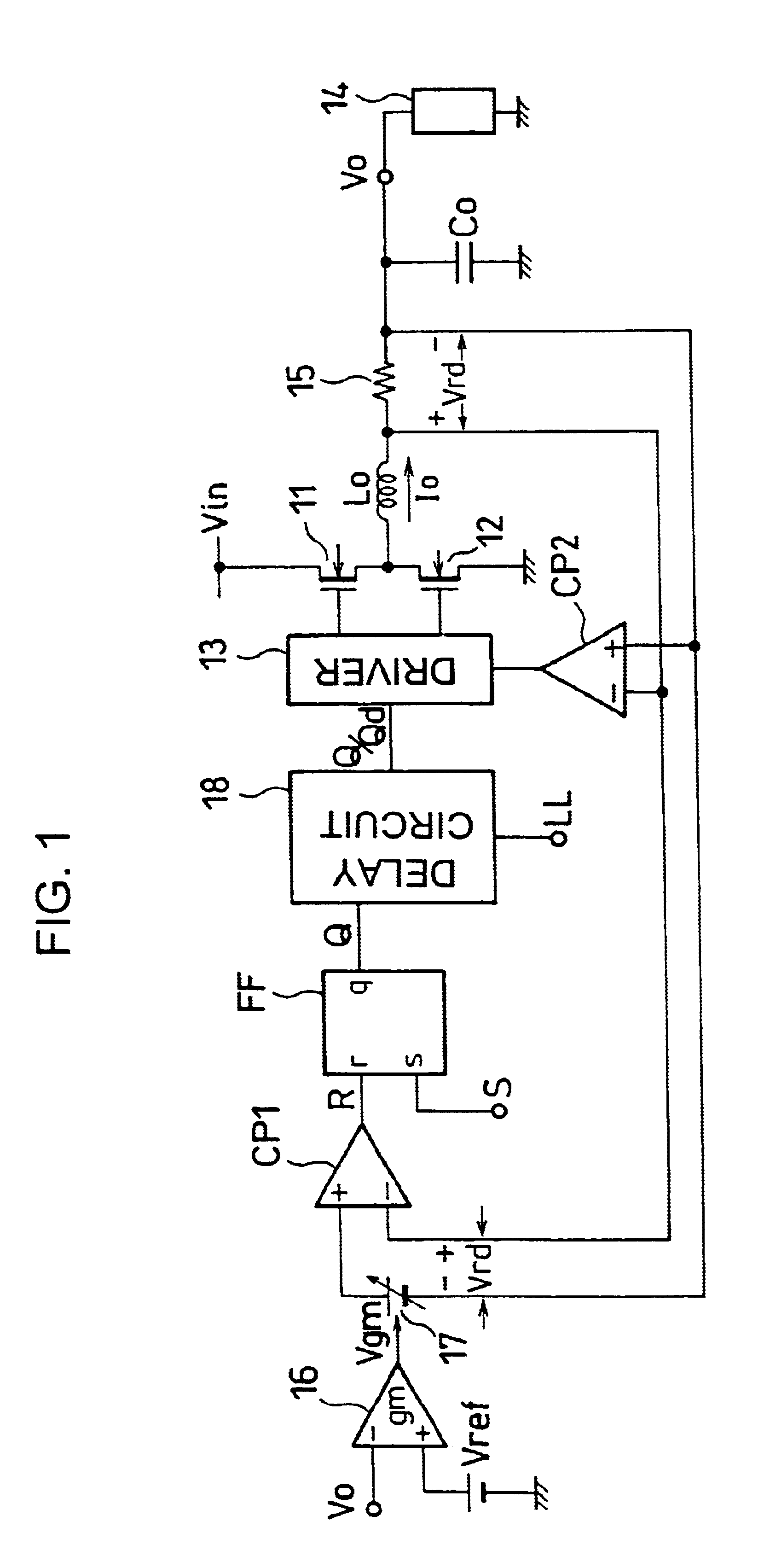
[0034]Referring to FIGS. 1-5, a first embodiment of a switching power supply unit of the invention will now be described.

[0035]As shown in FIG. 1, the switching power supply unit is formed as a current-control mode unit. An n-type MOS transistor 11 (referred to as n-type transistor) and another n-type transistor 12 connected in series between an input voltage Vin and the ground together form a switching circuit. The switching circuit is supplied with a driving pulse from a driver 13 and generally complementarily turns on and off the n-type transistors 11 and 12. A smoothing coil Lo smoothes the output of the switching circuit. An output condenser Co smoothes the output voltage Vo of the unit in collaboration with a smoothing coil Lo. The input voltage Vin is stepped down to the output voltage Vo in accordance with the pulse width of a given drive pulse. The output condenser Co is charged with the output voltage Vo. This output voltage Vo is supplied to a load 14. A resistor 15 is pr...


PUM


Abstract

A switching power supply unit generates a pulse signal having a duty factor based on the voltage associated with the difference between a reference voltage and the output voltage of the unit, and the voltage associated with the current flowing through a smoothing coil. Upon receipt of the pulse signal and a light-load determination signal, a delay-control unit of the power supply unit outputs as an instruction signal supplied to the switching circuit the pulse signal as it is when the light-load determination signal indicates that the load is not light, but otherwise outputs the pulse signal after delaying and widening the pulse width thereof. Thus, when the load is light, the switching power supply unit may hold its switching frequency substantially low and constant without rendering the frequency bursting discontinuously.

Description

[0001]This is a continuation of application Ser. No. 10 / 414,648 filed Apr. 16, 2003, now U.S. Pat. No. 6,815,939 which application is hereby incorporated by reference in its entirety.FIELD OF THE INVENTION[0002]The invention relates to a switching power supply unit having an improved power supply efficiency when operating under a light load.BACKGROUND OF THE INVENTION[0003]A switching power supply unit controls electric power that provides to a load by turning on and off a switch (e.g. power transistor) connected in series or parallel with the load. Such switching power supply unit uses a smoothing coil and an output condenser in order to stabilize a load current.[0004]The duty factor of the switch controlling the supply of electric power to the load is changed by, for example, regulating the period (or pulse width) of the on-state pulses while fixing the frequency of the pulses.[0005]Switching power supply units are in general more efficient than series power supply units. However,...

Claims


Application Information

Patent Timeline
Patent Type & Authority Patents(United States)
IPC IPC(8): H02M3/156H02M3/04H02M3/155
CPCH02M3/156H02M2001/0032H03F2200/351Y02B70/16Y02B70/10H02M1/0032
Inventor UMEMOTO, KIYOTAKATAKEMURA, KO
Owner ROHM CO LTD
Why Eureka
Try Eureka