Multiple stage sequential current regulator

a current regulator and multi-stage technology, applied in the direction of ignition automatic control, process and machine control, instruments, etc., can solve the problems of poor power factor, inconformity of line current harmonics, and inefficient operation

Active Publication Date: 2012-10-18
MICROCHIP TECH INC
View PDF3 Cites 71 Cited by
  • Summary
  • Abstract
  • Description
  • Claims
  • Application Information

AI Technical Summary

Benefits of technology

[0009]An LED driver circuit for controlling direct current supplied to a plurality of serially connected segments of Light Emitting Diodes (LEDs) receives current from a source of rectified alternating current voltage. The driver circuit comprises a plurality of current control elements, wherein each current control element has two ends. The first end of all the current control elements are connected to the return node of rectified alternating current voltage. A second end of each current control element is connected to a different end of each segment along the plurality of serially connected segments of LEDs. Each control element is enabled or disabled in sequence as the rectified AC voltage rises and falls. The sequencing of the current control elements is distributed among the control elements themselves, providing self-commutation and eliminating the need for a central sequencing circuit.

Problems solved by technology

A drawback of this circuit is the power dissipated in the current regulator (REG), which varies with line and load voltage, resulting in inefficient operation.
A further disadvantage is poor power factor as high current pulses are drawn from the AC source during peak charging of the energy storage capacitor (C).
These pulses generate line current harmonics which may not be in compliance with regional regulations.
Additionally, the storage capacitor (C) is a further drawback of this circuit since it typically is a high voltage electrolytic type which is bulky and subject to failures in high temperature environments.
Although the circuit with inductors is more efficient, a downside includes complex design, relatively high printed circuit board area, conducted EMI, and expensive components.
Electrolytic capacitors (CS) are especially troublesome as they are bulky and can be a major contributor to system failure.
The drawback of this method is that the predetermined voltage levels might not match the forward voltage drop of the LED segments.
Multiplied by the number of serially connected LEDs in the string can result in significant mismatch.
Premature enabling of a downstream control element with the simultaneous disabling of its' upstream neighbor occurs when there is not enough voltage to forward bias the LED segment, resulting in gaps in the input current waveform which may produce conducted EMI problems.
In addition, it results in underutilization of the LEDs.
Conversely, if the mismatch enables the control elements too late, it results in overlap and current spikes.
Other drawbacks include the need for additional circuitry, another high voltage connection to VRAC, and the need to employ LEDs with consistent forward voltage drop.

Method used


Image

  • Multiple stage sequential current regulator
  • Multiple stage sequential current regulator
  • Multiple stage sequential current regulator

Examples


Embodiment Construction

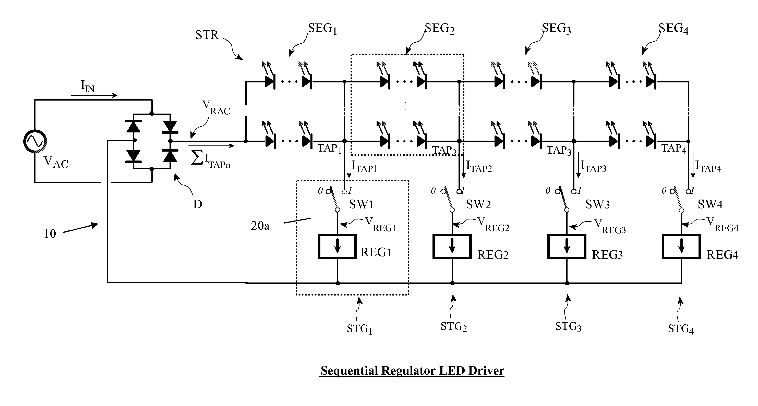
[0023]Referring to FIG. 3 there is shown a generalized schematic circuit diagram of an LED driver circuit 10 of the present invention. An AC voltage source (VAC) provides power to the driver circuit 10. In this example, a full-cycle rectifier (D), comprising of a full wave bridge rectifier with four diodes converts the alternating polarity of VAC to a positive voltage. This rectified AC voltage (VRAC) is provided to the top of the LED string (STR). The string is divided into segments (SEG1 thru SEG4), which are connected in series. Within each segment, the segment may consist of any combination of series and parallel connected LEDs, or even just a single LED. The junction between segments, including the bottom of the string (TAP1 thru TAP4) are connected to current control elements, or regulators (REG1 thru REG4). Switches SW1 thru SW4 are generalized elements allowing the regulators of each stage to be individually enabled / disabled. Alternatively, the circuit 10 can be a self commu...


PUM

PropertyMeasurementUnit
voltageaaaaaaaaaa
alternating current voltageaaaaaaaaaa
currentaaaaaaaaaa

Abstract

An LED driver circuit operating from the AC power line providing high efficiency, good line and load regulation, high power factor, low line current harmonics, low conducted EMI, high LED utilization, and lamp dimming compatibility, while consisting of a minimal number of components. No inductors, nor capacitors (including electrolytics), nor high current switching transistors are employed. The top of a string of series connected LED segments is connected to the output of a rectifier, which in turn is connected to an AC sine wave power source. The string is tapped at various locations, including the bottom of the string. Each segment can consists of any number of serial or parallel connected LEDs. Current control elements or regulators sink current at each tap and are sequentially turned on and off one at a time, tracking the rectified sine wave voltage. Voltage across each regulator and current when conducting is individually controllable. Power loss in the regulators is minimized by keeping regulator voltage to a minimum. The regulators may control current in a multitude of ways, including a constant current, or a current dependent on voltage across the regulators including a resistor, or a combination. The driver is self-commutating, with the sequencing of the current control elements an inherent feature closely integrated with the current control elements and providing optimal performance over variable operating conditions. Given the large number of design variables, the driver circuit can be optimized for various performance criteria including input voltage range, line / load regulation, output power / current, efficiency, power factor, line current harmonics, dimmer compatibility, and LED utilization.

Description

TECHNICAL FIELD[0001]This invention relates to constant current linear regulators, and more particularly to light emitting diode (LED) drivers that are powered from an alternating (AC) voltage source.BACKGROUND OF THE INVENTION[0002]To save energy, there is an effort to replace incandescent light bulbs with more efficient alternative light source. One alternative is the fluorescent lamp, especially the compact fluorescent lamp. While fluorescents addresses the energy issue, it introduces another concern. Fluorescent lamps, whether intended as a screw-in replacement for incandescent or as the traditional tube style, contain toxic mercury. This runs counter to a parallel effort to reduce toxic elements from our waste stream.[0003]Light emitting diodes (LED) are an alternative that do not contain mercury, are far more efficient than incandescent bulbs, and can surpass the efficiency of fluorescent bulbs. To be compatible with normal AC line voltage, however, special circuitry is needed...

Claims


Application Information

Patent Timeline
Patent Type & Authority Applications(United States)
IPC IPC(8): H05B37/02G05B24/02H05B44/00
CPCH05B33/0818H05B33/0827H05B33/0815Y02B20/347H05B33/083H05B45/48Y02B20/30H05B45/395H05B45/10H05B45/46
Inventor LYNCH, SCOTTCHOY, BENEDICT C.K.
Owner MICROCHIP TECH INC
Why Eureka
Try Eureka