Stroke amount detecting device

a stroke amount and detecting device technology, applied in galvano-magnetic devices, galvano-magnetic hall-effect devices, instruments, etc., can solve the problems of insufficient robustness, detection errors, detection errors, etc., and achieve linearity, improve the robustness of the stroke amount detecting device, improve the effect of stroke amoun

Active Publication Date: 2011-10-13
DENSO CORP
View PDF3 Cites 31 Cited by
  • Summary
  • Abstract
  • Description
  • Claims
  • Application Information

AI Technical Summary

Benefits of technology

[0012]In such a configuration, the first magnetic field generation member and the second magnetic field generation member are magnetized in opposite directions with respect to the direction perpendicular to the traveling axis. Likewise, the third magnetic field generation member and the fourth magnetic field generation member are magnetized in opposite directions with respect to the direction perpendicular to the traveling axis. As such, magnetic fluxes are repelled between the first magnetic field generation member and the second magnetic field generation member, and hence vectors of the magnetic fluxes are uniform along the traveling axis. Also, magnetic fluxes are repelled between the third magnetic field generation member and the fourth magnetic field generation member, and hence vectors of the magnetic fluxes are uniform along the traveling axis. In addition, the magnetosensitive surface of the magnetic sensor unit faces the direction along the traveling axis. Therefore, even if the magnetic sensor unit is displaced in a direction perpendicular to the traveling axis, a magnetic flux density detected by the magnetic sensor unit will not be affected. Accordingly, robustness of the stroke amount detecting device improves.
[0013]For example, linearity of the magnetic flux density to be detected by the magnetic sensor unit relative to an amount of stroke can be improved by adjusting arrangement positions of the first through fourth magnetic field generation members. That is, the linearity can be ensured by a magnetic circuit.

Problems solved by technology

In the magnetic position sensor described in JP2000-180114A, if the magnets are arranged such that the tapered surfaces are unevenly angled relative to a line along which the magnetic sensor element moves due to a machining error or an assembling error, detection errors may occur.
Further, in the case where the magnets opposed in the direction perpendicular to the stroke direction are magnetized in the same direction, as in the magnetic position sensor described in JP2000-180114A and the position detection device described in JP2008-45919A, if the position of the magnetic sensor element is displaced from the stroke direction, such as in the direction perpendicular to the stroke direction, a detecting magnetic flux density varies, resulting in detection errors.
Therefore, robustness will be insufficient.
That is, a property that a system characteristic maintains a current state against disturbances and errors in designing will be insufficient.

Method used


Image

  • Stroke amount detecting device
  • Stroke amount detecting device
  • Stroke amount detecting device

Examples


first embodiment

[0047]A stroke amount detecting device according to a first embodiment is employed to detect the amount of stroke of a stroking object. For example, the stroke amount detecting device is employed to detect the stroke amount of a stroking member, such as a transmission, an acceleration pedal, or a brake pedal of a vehicle.

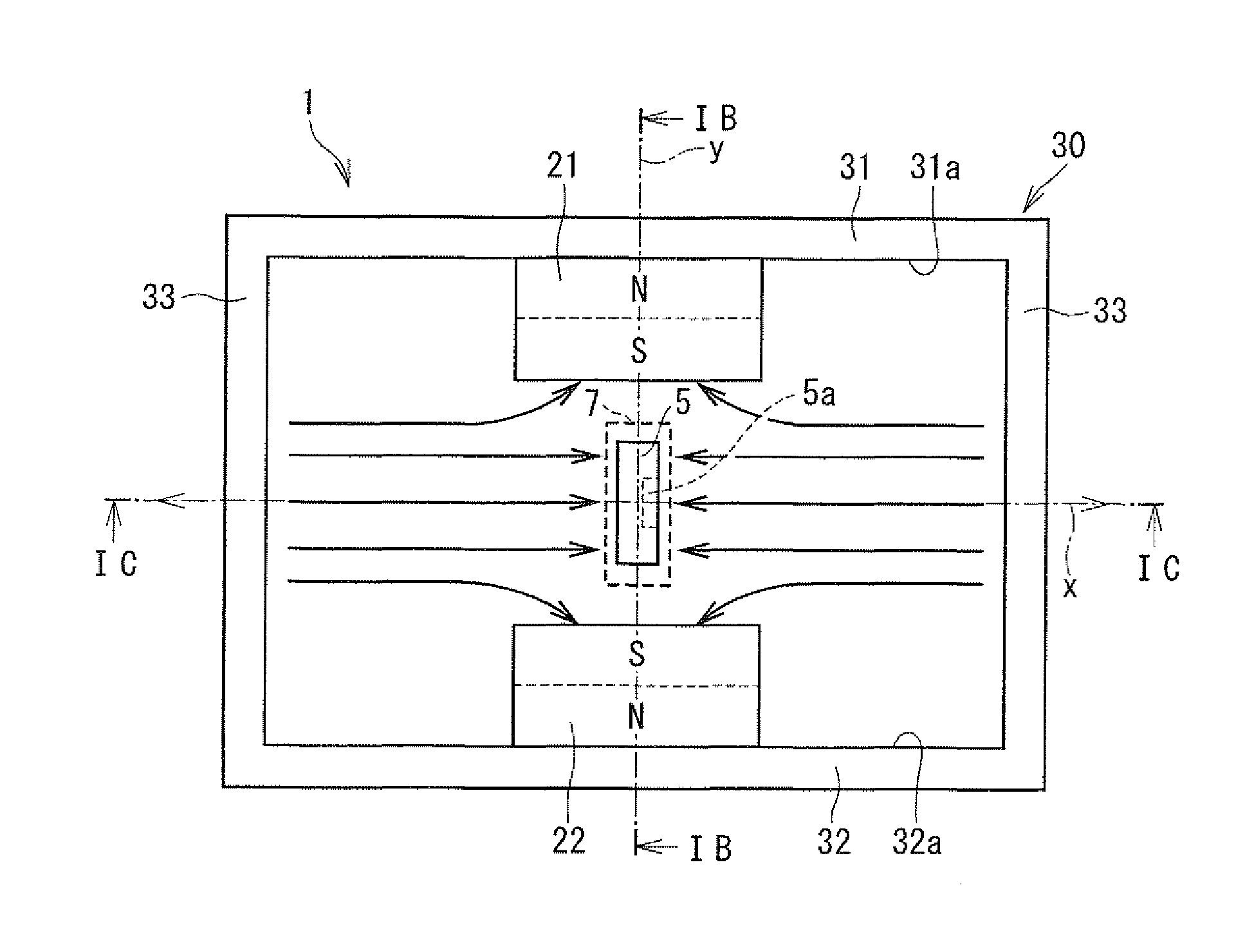
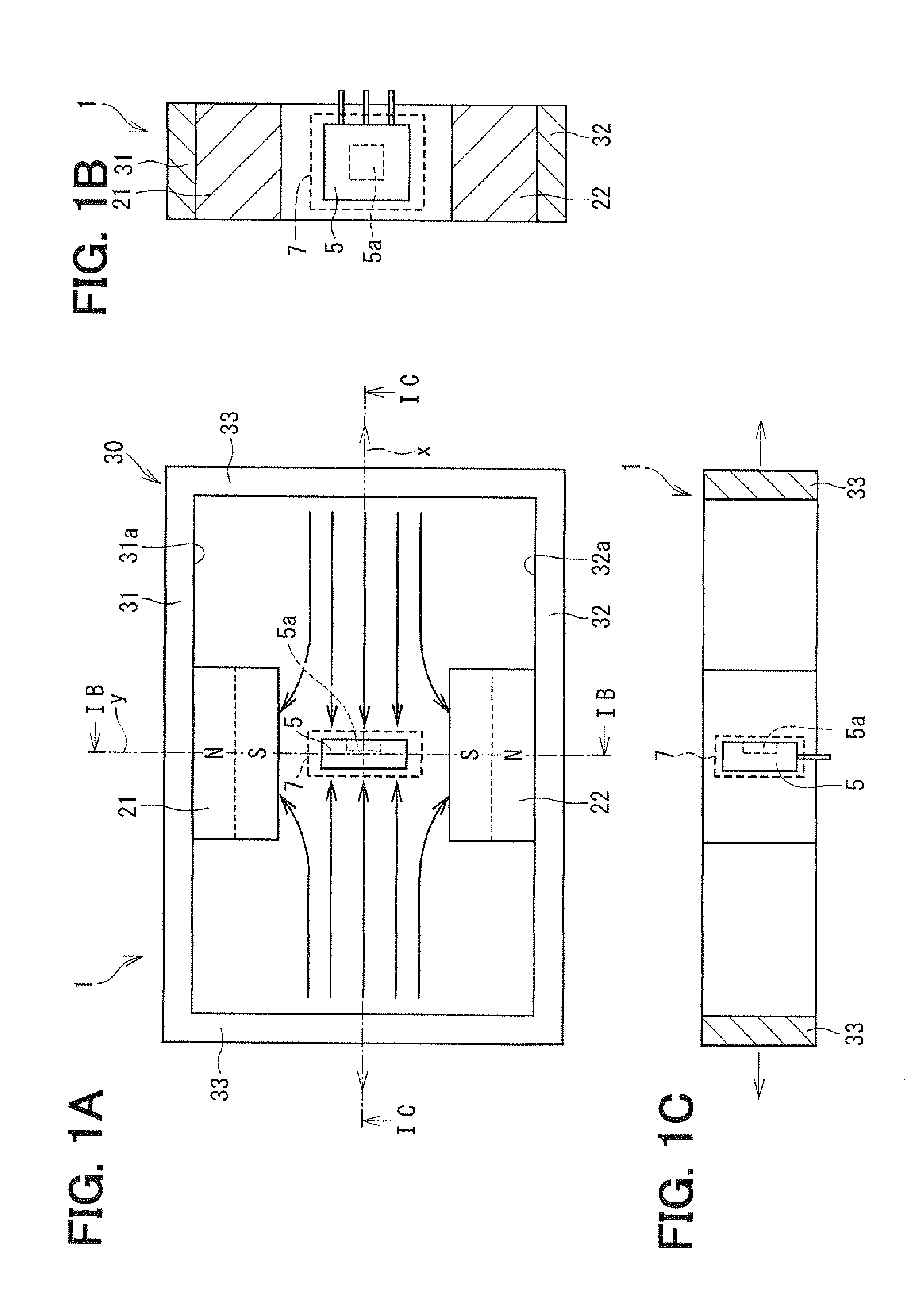
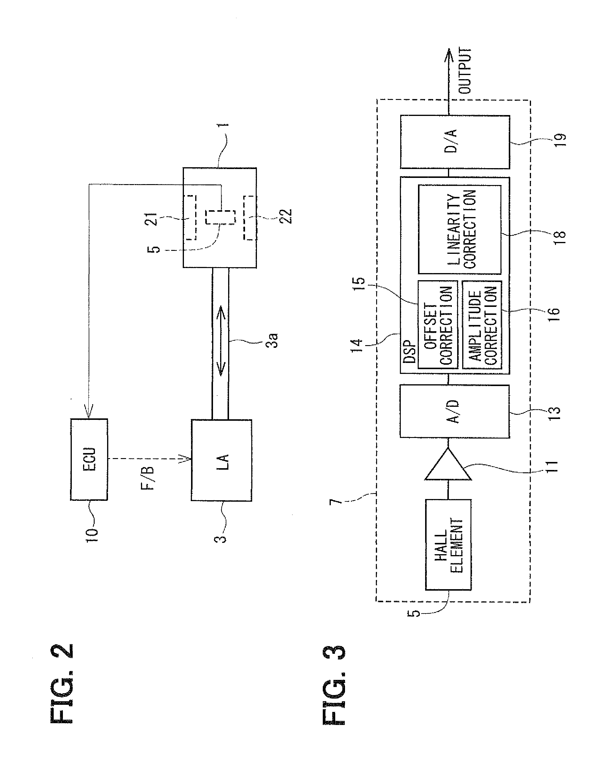
[0048]Referring to FIG. 2, a stroke amount detecting device 1 according to the first embodiment generally includes first and second magnets 21, 22 as examples of first and second magnetic field generation members, and a Hall element 5 as an example of a first sensor element. The Hall element 5 moves relative to the first and second magnets 21, 22 in accordance with a linear movement of a stroking member 3a of a linear actuator 3 so as to detect the stroke amount.

[0049]The detected stroke amount is sent to an engine control unit (ECU) 10. The ECU 10 utilizes the detected stroke amount to perform a feedback control of the linear actuator 3.

[0050]Next, a structure of t...

second embodiment

[0075]A second embodiment will be described with reference to FIGS. 5 and 6.

[0076]Referring to FIG. 5, the stroke amount detecting device 1 according to the second embodiment has a first magnet 25 and a second magnet 26, in place of the first magnet 21 and the second magnet 22 of the first embodiment. Each of the first magnet 25 and the second magnet 26 has a depressed shape including a thin portion 25a, 26a and thick portions 25b, 26b at opposite sides of the thin portion 25a, 26a.

[0077]The thin portion 25a is provided at a middle position of the stroke range, that is, in a range including the Y axis. The thick portions 25b are provided at opposite sides of the thin portion 25a with respect to the stroke direction. Each of the thick portions 25b has a thickness greater than the thickness of the thin portion 25a with respect to the Y direction. Thus, a distance between a surface of the thick portion 25b and the X axis is less than a distance between a surface of the thin portion 25...

third embodiment

[0082]A third embodiment will be described with reference to FIGS. 7, 8A and 8B. In the stroke amount detecting device 1 according to the third embodiment, as shown in FIG. 7, the first magnet 21 and the second magnet 22 are offset from the Y axis to a negative side of the stroke direction, that is, to a left side in FIG. 7.

[0083]For example, in a case where the stroke range of the stroking object is biased toward the negative side from the reference point, the first magnet 21 and the second magnet 22 are arranged on the negative side to be adjacent to the center of the stroke range. Thus, an accurate range can be selectively utilized as centering the point where the magnetic flux density is zero.

[0084]In FIG. 7, an arrow Le represents a detectable range (detection available range) in which the magnetic flux density can be detected by the Hall element 5 and an arrow Lu represents an undetectable range in which the magnetic flux density cannot be detected by the Hall element 5. As sh...


PUM


Abstract

A stroke amount detecting device includes a first magnetic field generation member, a second magnetic field generation member, and a magnetic sensor unit. The first magnetic field generation member and the second magnetic field generation member are opposed to each other with respect to a direction perpendicular to a straight stroking axis of a stroking object, and magnetized in opposite directions. The magnetic sensor unit is movable in an area between the first magnetic field generation member and the second magnetic field generation member, along a straight traveling axis that is parallel to the straight stroking axis relative to the first magnetic field generation member and the second magnetic field generation member in accordance with a stroke motion of the stroking object. The magnetic sensor unit has a magnetosensitive surface facing a direction parallel to the traveling axis, thereby to detect an amount of stroke of the object.

Description

CROSS REFERENCE TO RELATED APPLICATION[0001]This application is based on Japanese Patent Application No. 2010-89284 filed on Apr. 8, 2010, the disclosure of which is incorporated herein by reference.FIELD OF THE INVENTION[0002]The present invention relates to a stroke amount detecting device for detecting the amount of stroke of a stroking object.BACKGROUND OF THE INVENTION[0003]In a conventional stroke amount detecting device, a magnetic sensor element moves relative to a magnet as a magnetic field generation member in accordance with a linear movement of a stroking object. The amount of stroke of the object is detected based on an output signal generated from the magnetic sensor element. For example, JP2000-180114A, which corresponds to U.S. Pat. No. 6,211,668, and JP2008-45919A describe inventions for improving linearity of output signals relative to the stroke amount.[0004]In a magnetic position sensor described in JP2000-180114A, tapered magnets are opposed to each other in a d...

Claims


Application Information

Patent Timeline
Patent Type & Authority Applications(United States)
IPC IPC(8): G01B7/14
CPCG01D5/145
Inventor MATSUMOTO, KOICHIROKONO, YOSHIYUKIHONDA, HITOMI
Owner DENSO CORP
Why Eureka
Try Eureka