High-performance piston core for a magnetorheological damper

a technology of magnetorheological dampers and piston cores, which is applied in the direction of shock absorbers, fluid couplings, rotary clutches, etc., can solve the problems of limiting the dynamic range and performance of the mr damper, the cost of suitable high-performance magnetic alloys such as cobalt steel and vanadium/cobalt steel (permendur), and the cost of low-carbon steel used presently, so as to achieve high magnetic flux density.

Active Publication Date: 2005-09-27
DELPHI TECH INC +1
View PDF2 Cites 32 Cited by
  • Summary
  • Abstract
  • Description
  • Claims
  • Application Information

AI Technical Summary

Benefits of technology

[0010]One aspect of the present invention provides a high-performance piston core for a magnetorheological damper that provides a high magnetic flux density in the flow gap.

Problems solved by technology

The high flux density region 22 restricts the magnetic flux through the central portion of the core, acting as a flux bottleneck, and thus limits the dynamic range and performance of the MR damper.
The cost of suitable high-performance magnetic alloys, such as Cobalt steel and Vanadium / Cobalt steel (Permendur), greatly exceeds the cost of low-carbon steel used presently.
The increased cost makes this approach uneconomical for mass-produced items, such as automotive dampers, which are produced in large numbers and for which even a small fractional cost determines profit or loss.
This increases the flux density in the flow gap for a given number of ampere-turns in the coil winding, but precludes desirable damper configurations.
This causes a number of materials problems, such as particle separation, particle sedimentation, increased abrasion, and increased viscosity.
The increased iron content causes operational difficulties, such as greater magnetic field loss and reduction in damper dynamic range.
The required increased gap width in turn reduces the flux density in the flow gap, thus negating the benefits of increased iron content in the fluid.
Increased iron content also increases MR fluid cost.
The many problems resulting from increased iron content in the MR fluid make this approach undesirable.

Method used


Image

  • High-performance piston core for a magnetorheological damper
  • High-performance piston core for a magnetorheological damper
  • High-performance piston core for a magnetorheological damper

Examples


Embodiment Construction

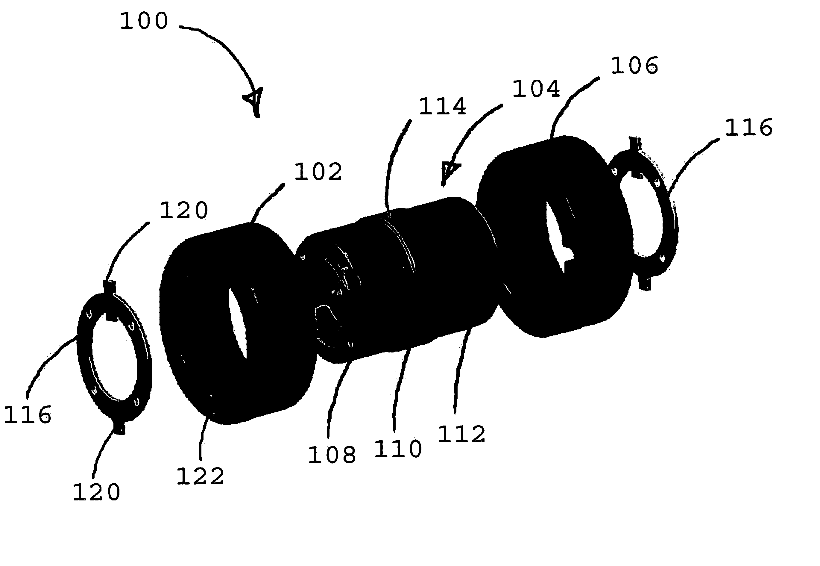
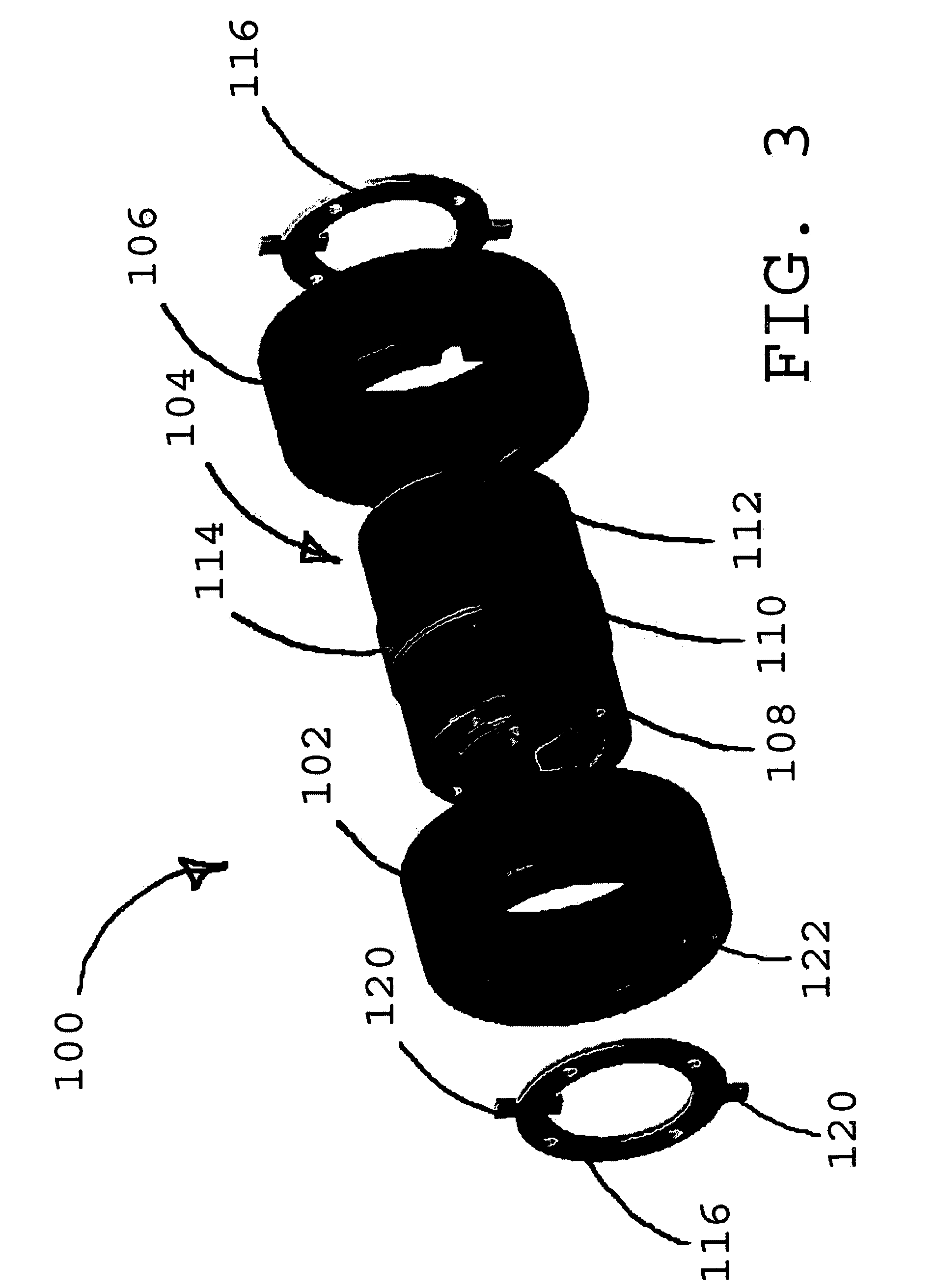
[0023]The high-performance piston core for a magnetorheological damper of the present invention attains the magnetic characteristics of a piston core made completely of high-performance magnetic material while minimizing the amount of high-performance magnetic material actually used. The high-performance piston core provides greater flux density in the damper flow gap, greater damping force, and greater damper dynamic range. The high-performance piston core also provides improved dynamic response through the reduced persistence of eddy currents when coil current is changed.

[0024]FIGS. 3–5 show an exploded perspective, a cross section, and a flow gap radial flux density plot, respectively, for a high-performance piston core for a magnetorheological damper. The piston core uses high-performance magnetic materials in flux bottleneck directly below the coil winding gap and in the piston cylinders to reduce the magnetic reluctance in the flux bottleneck.

[0025]FIGS. 3 & 4, in which like e...


PUM

PropertyMeasurementUnit
diameteraaaaaaaaaa
diameteraaaaaaaaaa
diameteraaaaaaaaaa

Abstract

A high-performance piston core including a first piston cylinder and a second piston cylinder, with a piston center longitudinally disposed between and magnetically coupling the first piston cylinder and the second piston cylinder. The piston center is made of high-performance magnetic material, such as Cobalt steel (CoFe), Silicon steel (SiFe), Vanadium/Cobalt steel (Permendur), alloys thereof, or the like. The high-performance magnetic materials exhibit high magnetic permeability and reduce the magnetic reluctance of flux bottlenecks. In addition, high-performance magnetic materials typically saturate at a higher flux density than the conventional magnetic materials. The first piston cylinder and the second piston cylinder can be made of conventional magnetic material, such as low-carbon steel. The first piston cylinder can include a ring disposed about an end, where the end is longitudinally attached and magnetically coupled to the piston center.

Description

TECHNICAL FIELD[0001]This invention relates generally to the field of magnetorheological fluid dampers, and in particular, to high-performance piston cores for use in magnetorheological fluid dampers.BACKGROUND OF THE INVENTION[0002]Magnetorheological fluid dampers have found a number of practical applications in automotive suspensions, clutches, engine mounts, vibration control units, earthquake proofing equipment, and robotic systems. The magnetorheological fluid in the damper changes key rheological properties, such as yield stress or viscosity, in response to a magnetic flux to adjust the damping characteristics of the damper.[0003]FIG. 1 shows a cutaway perspective view for a magnetorheological (MR) piston including a piston core. Magnetorheological (MR) dampers have a cylinder (not shown) containing an MR fluid and an MR piston 10 slidably engaging the inner diameter of the cylinder. In this example, the MR fluid passes through a flow gap 12 between the inner surface of solid ...

Claims


Application Information

Patent Timeline
Patent Type & Authority Patents(United States)
IPC IPC(8): F16D37/02F16D37/00F16F9/53F16F9/32
CPCF16F9/3214F16F9/535
Inventor GOLDASZ, JANUSZ P.SZKLARZ, ZBIGNIEW W.ALEXANDRIDIS, ALEXANDER A.NEHL, THOMAS W.DENG, FANGVALEE, OLIVIER
Owner DELPHI TECH INC
Why Eureka
Try Eureka