
Image scanning apparatus, and method and computer-readable medium therefor

a scanning apparatus and image technology, applied in the field of image scanning apparatus, and a non-transitory computerreadable medium therefor, can solve the problem of longer interval between

Active Publication Date: 2018-10-04
BROTHER KOGYO KK
View PDF0 Cites 3 Cited by
  • Summary
  • Abstract
  • Description
  • Claims
  • Application Information

AI Technical Summary

Benefits of technology

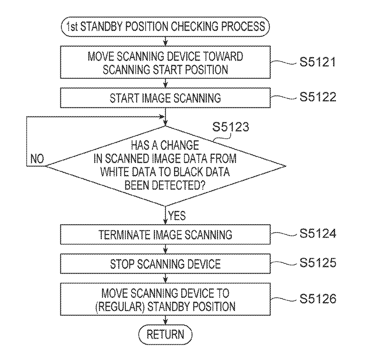
The patent text describes an image scanning apparatus that can correct itself to ensure the carriage returns to the predetermined home position accurately. This allows the carriage to start moving from the scanning start position. However, repeatedly determining if the apparatus returns to the home position each time it reaches the standby position can result in longer intervals between the end of previous scanning and the start of the next.

Problems solved by technology

However, determining whether the image scanning apparatus returns to the predetermined home position exactly each time the carriage returns to the standby position may result in a longer interval between an end of previous image scanning and a start of next image scanning.

Method used


Image

  • Image scanning apparatus, and method and computer-readable medium therefor
  • Image scanning apparatus, and method and computer-readable medium therefor
  • Image scanning apparatus, and method and computer-readable medium therefor

Examples


Embodiment Construction

[0020]It is noted that various connections are set forth between elements in the following description. It is noted that these connections in general and, unless specified otherwise, may be direct or indirect and that this specification is not intended to be limiting in this respect. Aspects of the present disclosure may be implemented on circuits (such as application specific integrated circuits) or in computer software as programs storable on computer-readable media including but not limited to RAMs, ROMs, flash memories, EEPROMs, CD-media, DVD-media, temporary storage, hard disk drives, floppy drives, permanent storage, and the like.

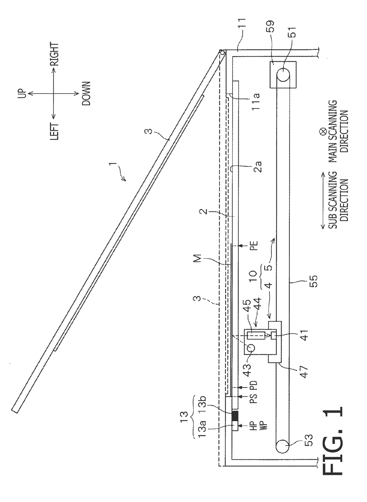
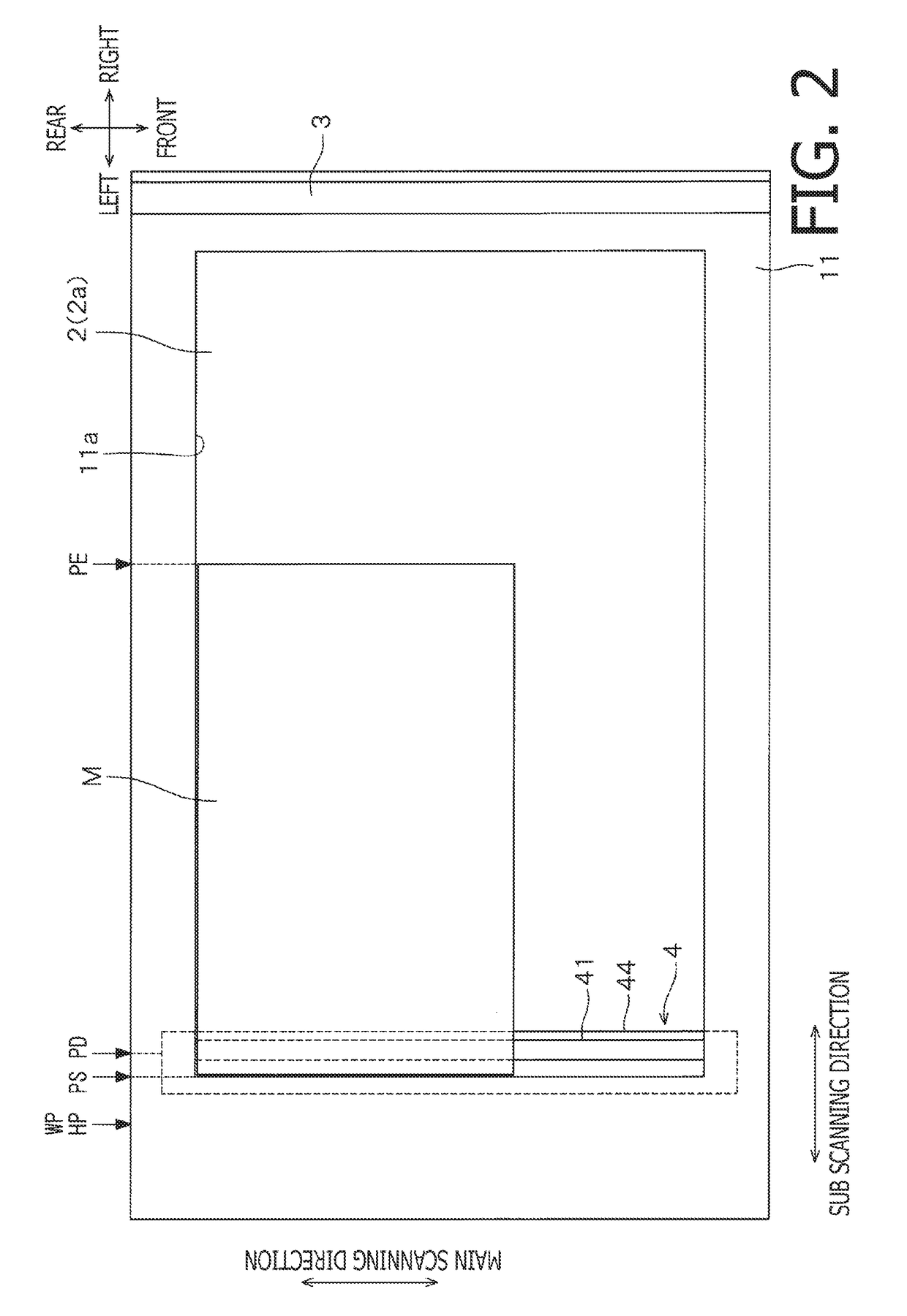
[0021]Hereinafter, an image scanning apparatus 1 of an illustrative embodiment according to aspects of the present disclosure will be described with reference to the accompanying drawings. In the following description, a left-to-right direction, a front-to-rear direction, and a vertical direction of the apparatus 1 may be defined as shown in FIGS. 1 a...


PUM


Abstract

An image scanning apparatus includes a controller configured to execute a first operation of checking whether a standby position is coincident with a home position in response to determining that an open signal is not output from a cover sensor while an image scanner is changing a scanning position from a scanning end position toward a scanning start position after completion of image scanning, and to execute a second operation in response to determining that the open signal is output from the cover sensor while the image scanner is changing the scanning position, the second operation including moving the scanning position to a particular position between the standby position and the scanning end position, without executing the first operation.

Description

CROSS-REFERENCE TO RELATED APPLICATION[0001]This application claims priority under 35 U.S.C. § 119 from Japanese Patent Application No. 2017-073324 filed on Apr. 1, 2017. The entire subject matter of the application is incorporated herein by reference.BACKGROUNDTechnical Field[0002]Aspects of the present disclosure are related to an image scanning apparatus, and a method and a non-transitory computer-readable medium therefor.Related Art[0003]Heretofore, a flatbed type image scanning apparatus has been known. The known apparatus includes a document table having a glass plate, a document cover, a carriage, and a CIS unit (“CIS” is an abbreviation of “Contact Image Sensor”) mounted on the carriage. The document cover is openable and closable relative to the document table. The carriage is configured to reciprocate along a particular direction under the document table.[0004]The user opens the document cover, sets the document sheet on the document table, and closes the document cover to...

Claims


Application Information

Patent Timeline
Patent Type & Authority Applications(United States)
IPC IPC(8): H04N1/00H04N1/10H04N1/047H04N1/031
CPCH04N1/00551H04N1/1061H04N1/00408H04N1/0473H04N1/0311
Inventor MAEDA, TAKASHI
Owner BROTHER KOGYO KK
Learn More