
Wireless communication system and wireless communication method

a wireless communication and wireless communication technology, applied in the field of wireless communication system and wireless communication method, can solve the problems of reducing throughput, reducing transmission opportunity (an opportunity to obtain channel access rights), and reducing throughput, so as to improve throughput, stop demodulation processing, and increase transmission opportunity

Active Publication Date: 2018-10-04
NIPPON TELEGRAPH & TELEPHONE CORP
View PDF1 Cites 2 Cited by
  • Summary
  • Abstract
  • Description
  • Claims
  • Application Information

AI Technical Summary

Benefits of technology

The present invention relates to a method for improving data transmission in a wireless network. It involves dynamically adjusting a CCA threshold based on interference power to increase transmission opportunities and improve throughput. The method also enables simultaneous transmissions while ensuring reliable reception of management frames, such as beacon frames, and avoids throughput decrease for Non-HE stations or frames not in an HE format. The technical effects of the invention include increasing transmission opportunities, improving throughput, and ensuring reliable reception of management frames.

Problems solved by technology

In that case, due to interference among the BSSs that use the same channel, throughput of the BSS and throughput of an entire system are decreased.
However, although the CSMA / CA protocol is performed, in the wireless LAN high density environment where many wireless LAN networks use the same channel, because the frequency with which the channel is busy due to the carrier sense is increased, a transmission opportunity (an opportunity to obtain the channel access right) is reduced, and throughput is reduced.
However, if the STA 1 is located near the AP 2 and an interference signal from the AP 2 is large in magnitude, although the control of the CCA threshold in the AP 1 causes the transmission opportunity of the AP1 to be increased, there is a concern that a receive failure will occur in the STA 1 due to the interference signal from the AP 2, thereby instead decreasing throughput.

Method used


Image

  • Wireless communication system and wireless communication method
  • Wireless communication system and wireless communication method
  • Wireless communication system and wireless communication method

Examples


first embodiment

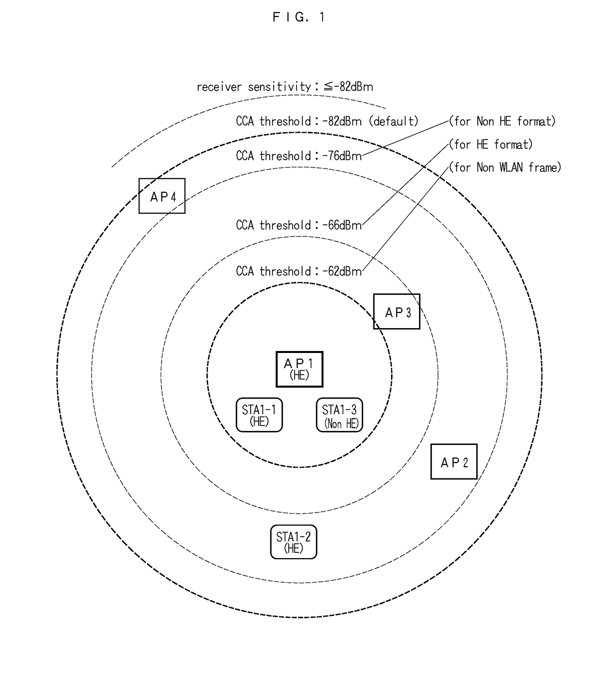
[0064]In the first embodiment, it is assumed that all stations which have to perform communication with the AP 1 are placed within a range of a single-digit meter in which tethering is performed. For example, in FIG. 1, if only the STA 1-1 and the STA 1-3 are present in the vicinity of the AP 1, receiver sensitivity of the AP 1, for example, is set to −62 dBm or more. Accordingly, it is possible that the AP 1 performs simultaneous transmissions to the STA 1-1 and the STA 1-3 more simply than the AP 1 controls the CCA threshold.

[0065]A control server, which is connected to each AP in a shared manner and in a wired or wireless manner, can set receiver sensitivity that corresponds to a communication area, which is controlled by each AP. In FIG. 1, the AP 1 measures receive signals from the STA 1-1 and the STA 1-3 or RSSIs of wireless signals that are transmitted from the AP 2 to AP 4 in the vicinity, and notifies the control server of results of the measurement. If the RSSIs from the S...

second embodiment

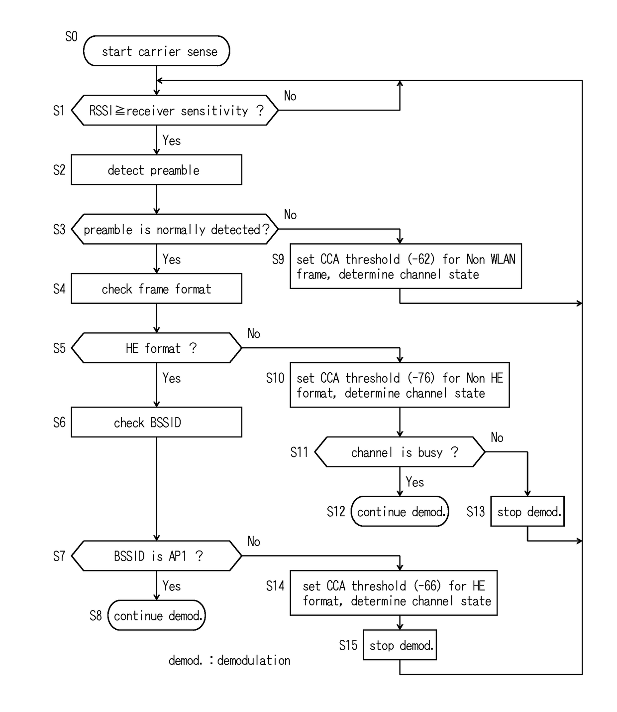
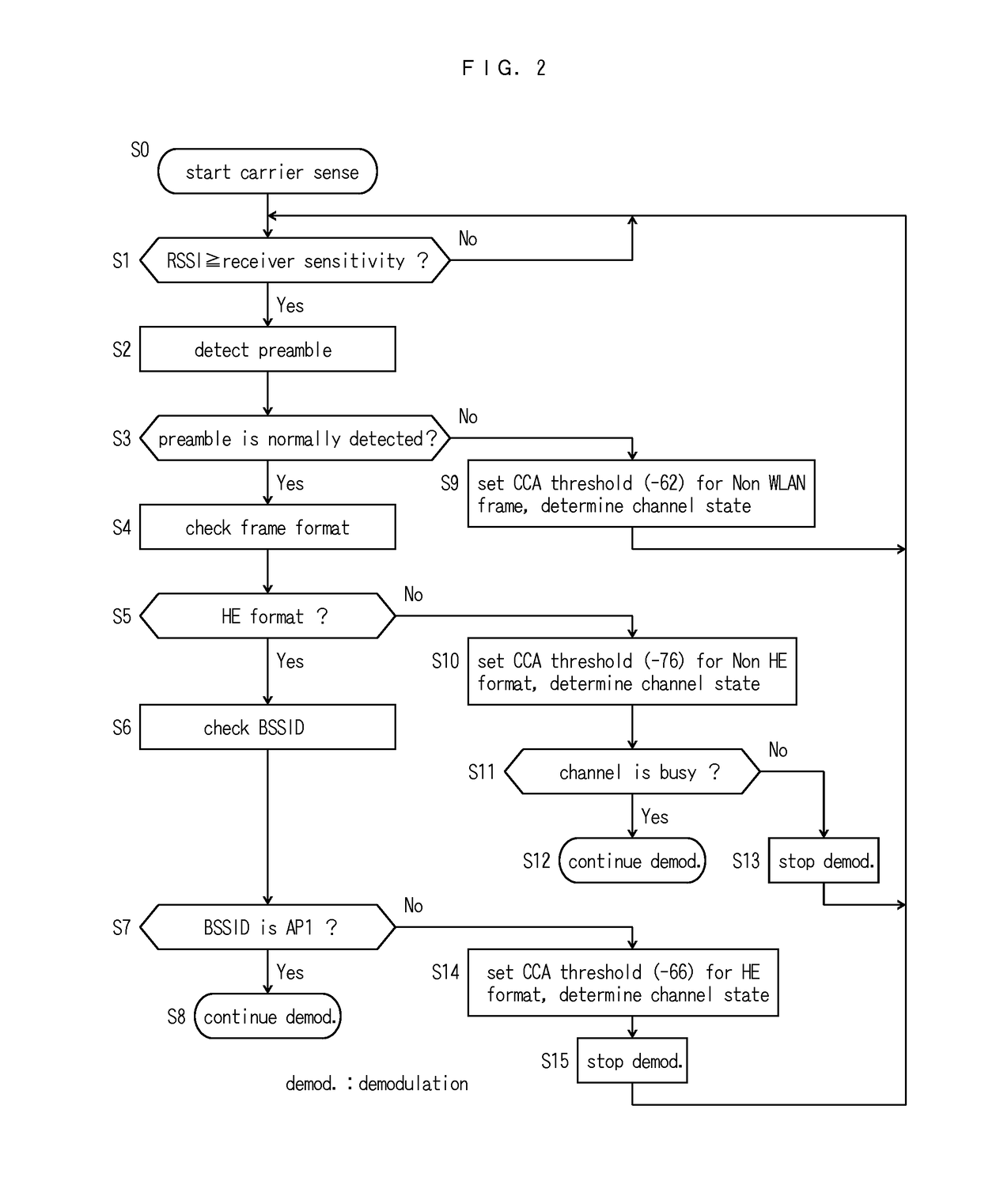
[0067]A feature of the second embodiment is that a CCA threshold of each receive frame format in the AP 1 is controlled. At this point, the CCA threshold is controlled to be a high value, for example, −66 dBm that is illustrated in FIG. 1, in such a manner that the simultaneous transmissions are positively performed in a frame in the HE format. From the perspective of the fairness, when it comes to a frame in the Non-HE format, the CCA threshold is controlled to be a default value, for example, −82 dBm that is illustrated in FIG. 1, or to be a value that is lower than the CCA threshold for the HE format, for example, −76 dBm that is illustrated in FIG. 1. It is noted that the CCA threshold for the HE format may be set to be in a fixed relationship to the CCA threshold for the Non-HE format, for example, be set to be higher by 10 dB, and so forth.

[0068]FIG. 2 illustrates a first example of a procedure for the AP 1 to perform receiving processing in the second embodiment of the presen...

third embodiment

[0097]A feature of the third embodiment is that each type of the receive frame in the AP 1 is controlled. At this point, a frame type is read when receiving the frame, and is received and demodulated as is. However, the demodulation is stopped, and thus, it is selected whether or not the simultaneous transmissions are set to be possible. For example, if a data frame is received, the simultaneous transmissions are positively performed. Although a frame of another BSS is present, if a management frame is present such as a beacon frame of the AP or an association request frame of the STA, the simultaneous transmissions are kept from being performed, and the reception and the demodulation are preferentially performed. It is noted that because a control frame, such as an RTS, a CTS, or an ACK, has a short frame time length, the advantage of switching the control to the simultaneous transmissions is so small that the control frame may be received and demodulated as is and may be utilized ...


PUM


Abstract

A format that includes a BSSID of a transmitting station within a preamble of the frame is an HE format, and a format that does not include a BSSID within the preamble but includes a BSSID in a MAC header is a Non-HE format; and a wireless station in the BSS includes a control part which checks a format of a frame received at a predetermined receiver sensitivity or above, and continues demodulation of the received frame if the format is HE format and the BSSID in the received frame is consistent with its own BSS, and stops the demodulation of the received frame if the HE format and the BSSID in the received frame is not consistent with its own BSS.

Description

CROSS REFERENCE TO RELATED APPLICATION[0001]This application is a U.S. National Stage application claiming the benefit of prior filed International Application Number PCT / JP2016 / 079667, filed on Oct. 5, 2016, in which the International Application claims priority from Japanese Patent Application Number 2015-197969, filed on Oct. 5, 2015, the entire contents of which are incorporated herein by reference.TECHNICAL FIELD[0002]The present invention relates to a wireless communication system and a wireless communication method that mitigates a decrease in throughput due to carrier sense multiple access with collision avoidance (CSMA / CA) protocol carried out by each wireless station, in a wireless local area network (LAN) high density environment.BACKGROUND ART[0003]In recent years, with the spread of a high-performance portable wireless station, such as a notebook computer or a smartphone, wireless LANs in compliance with the IEEE 802.11 standard have come into wide use not only in compa...

Claims


Application Information

Patent Timeline
Patent Type & Authority Applications(United States)
IPC IPC(8): H04W74/08H04W72/08H04W28/06H04L1/00
CPCH04W74/0816H04W72/082H04W28/06H04L1/0021H04W48/02H04W16/08H04W28/065H04W72/541H04W84/12H04W74/0808H04W72/54
Inventor SHINOHARA, SHOKOINOUE, YASUHIKOIWATANI, JUNICHIMIZOGUCHI, MASATO
Owner NIPPON TELEGRAPH & TELEPHONE CORP
Learn More