
Vacuum cleaner

a vacuum cleaner and vacuum technology, applied in the field of vacuum cleaners, can solve the problems of inability to detect the size and shape of obstacles, the area to be cleaned, and the inability to clean, etc., and achieve the effect of high precision

Inactive Publication Date: 2018-10-11
TOSHIBA LIFESTYLE PROD & SERVICES CORP
View PDF1 Cites 9 Cited by
  • Summary
  • Abstract
  • Description
  • Claims
  • Application Information

AI Technical Summary

Benefits of technology

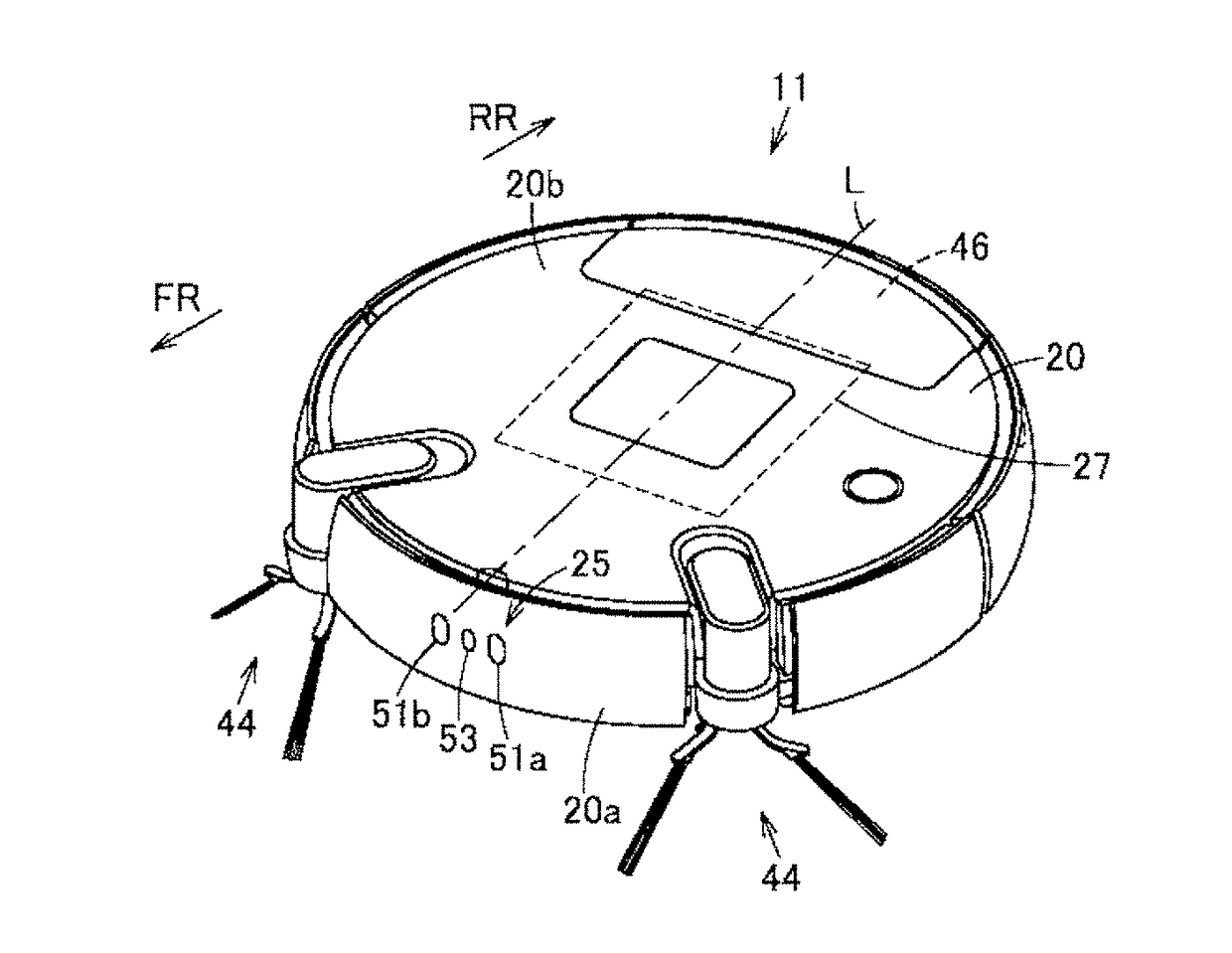
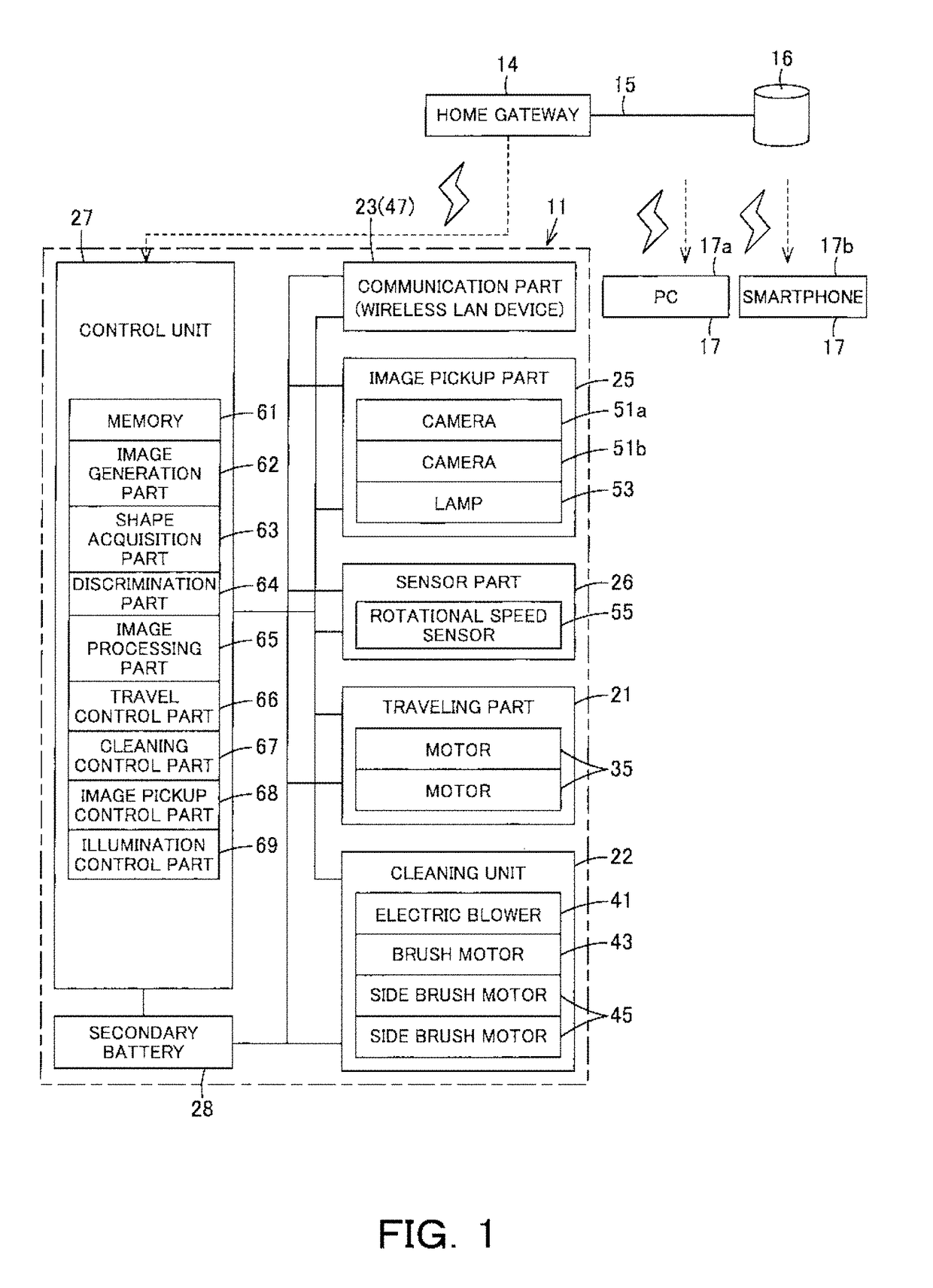
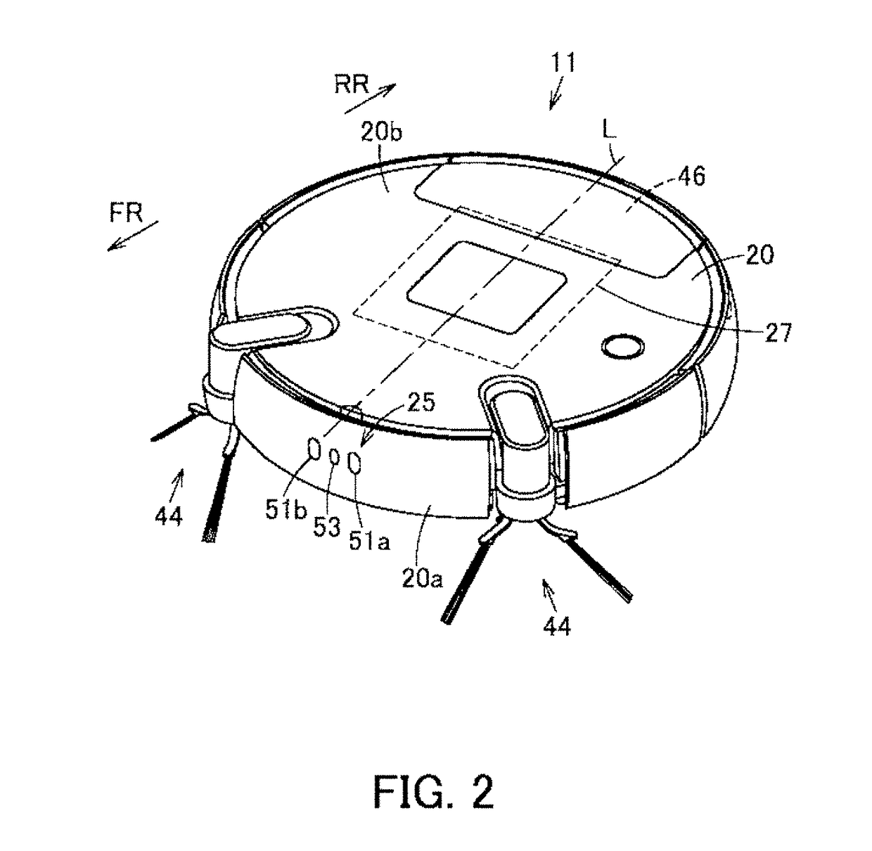
The vacuum cleaner described in this patent has a camera setup that allows it to autonomously move around and capture images of its surroundings. It can also generate a distance image of an object using those images and acquire shape information about that object. This allows for accurate positioning and navigation based on the information captured by the vacuum cleaner's camera system.

Problems solved by technology

However, in the cases where these sensors are used, presence of obstacles can be detected, but it is not easy to detect the size and shape of the obstacles.
Thus, the area to be cleaned is limited, causing stagnation in cleaning.

Method used


Image

  • Vacuum cleaner
  • Vacuum cleaner
  • Vacuum cleaner

Examples


Embodiment Construction

[0019]Hereinbelow, the constitution of an embodiment will be described with reference to the accompanying drawings.

[0020]In FIG. 1 to FIG. 4, reference sign 11 denotes a vacuum cleaner, and this vacuum cleaner 11 constitutes a vacuum cleaner device (vacuum cleaner system) in combination with a charging device (charging stand) 12 (FIG. 4) as abase device serving as a base station for charging of the vacuum cleaner 11. Then, the vacuum cleaner 11 is, in this embodiment, a so-called self-propelled robot cleaner (cleaning robot) which cleans a floor surface that is a cleaning-object surface as a traveling surface while autonomously traveling (self-propelled to travel) on the floor surface, and it is enabled to perform wired or wireless communication with a general-purpose server 16 as data storage means (a data storage part) or a general-purpose external device 17 as display means (a display part) via an (external) network 15 such as the Internet or the like by, for example, performing ...


PUM


Abstract

A vacuum cleaner capable of detecting a shape of an object with high precision. A vacuum cleaner includes a main casing, driving wheels, a control unit, a plurality of cameras, an image generation part, and a shape acquisition part. The driving wheels enable the main casing to travel. The control unit controls drive of the driving wheels to make the main casing autonomously travel. The cameras are disposed apart from each other in the main casing to pick up images on a traveling-direction side of the main casing. The image generation part generates a distance image of an object positioned on the traveling-direction side based on the images picked up by the cameras. The shape acquisition part acquires the shape information of the picked-up object from the distance image generated by the image generation part.

Description

TECHNICAL FIELD[0001]Embodiments described herein relate generally to a vacuum cleaner including a plurality of image pickup means for picking up images on a traveling-direction side of a main casing.BACKGROUND ART[0002]Conventionally, a so-called autonomous-traveling type vacuum cleaner (cleaning robot) which cleans a floor surface as a cleaning-object surface while autonomously traveling on the floor surface has been known.[0003]Such a vacuum cleaner is required to avoid obstacles during its traveling. For this reason, the vacuum cleaner uses sensors, such as ultrasonic sensors and infrared sensors, for detection of obstacles which obstruct traveling. However, in the cases where these sensors are used, presence of obstacles can be detected, but it is not easy to detect the size and shape of the obstacles.[0004]In such an autonomous-traveling type vacuum cleaner, in the cases where the vacuum cleaner is unable to detect the size and shape of an obstacle, it is required to travel wh...

Claims


Application Information

Patent Timeline
Patent Type & Authority Applications(United States)
IPC IPC(8): A47L9/00G05D1/02
CPCA47L9/009G05D1/0246G05D1/0255A47L9/28G01B11/14A47L2201/04G05D1/0242G05D1/024G05D2201/0215G05D1/0212G06T1/00G01B11/026H04N13/239A47L9/2805A47L9/2852H04N13/207G01B11/24
Inventor IZAWA, HIROKAZUMARUTANI, YUUKIWATANABE, KOTAFURUTA, KAZUHIRO
Owner TOSHIBA LIFESTYLE PROD & SERVICES CORP
Learn More