Electron Beam Generation for Transmission Electron Microscope

a technology of transmission electron microscope and electron beam, which is applied in the direction of basic electric elements, electric discharge tubes, electrical apparatus, etc., can solve the problems of limited energy spread that can be achieved with prior techniques, and prior methods are not suitable for high-resolution transmission electron microscopy, and achieves the same energy spread, superior beam properties, and sub-ev energy spread

Active Publication Date: 2018-10-18
TECH UNIV EINDHOVEN
View PDF1 Cites 4 Cited by
  • Summary
  • Abstract
  • Description
  • Claims
  • Application Information

AI Technical Summary

Benefits of technology

[0014]Advantageously, this new type of Transmission Electron Microscope (TEM) with superior beam properties, based on relatively cheap technology, can be realized without the need of high-voltage electrostatic acceleration, while retaining sub-eV energy spread.
[0015]By using RF cavities for accelerating electrons, cumbersome high voltage techniques are no longer needed. By using a second set of RF cavities oscillating 90 degrees out of phase, the same energy spread, or even a lower energy spread, can be achieved as with high voltage electrostatic acceleration.

Problems solved by technology

Moreover, the smallest energy spread that can be achieved with prior techniques is limited by the stability of the microwave generator.
For this reason these prior methods would not be suitable for high-resolution transmission electron microscopy.

Method used


Image

  • Electron Beam Generation for Transmission Electron Microscope
  • Electron Beam Generation for Transmission Electron Microscope
  • Electron Beam Generation for Transmission Electron Microscope

Examples


Embodiment Construction

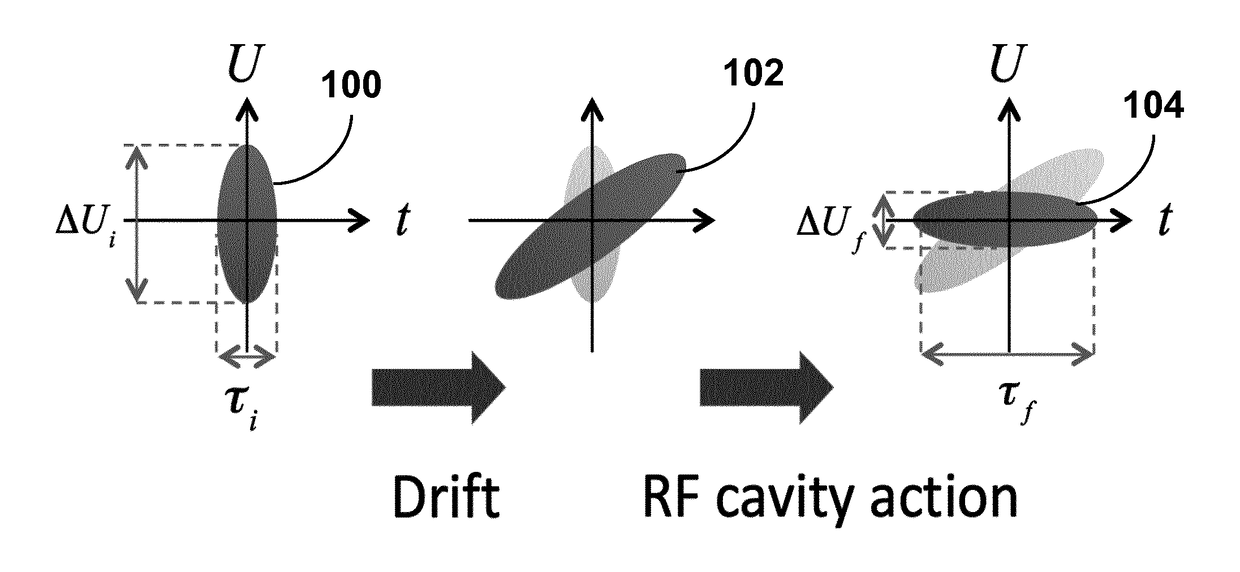
[0020]The invention provides techniques for producing electron beams with very high energy stability using resonant RF cavities. In one aspect, two RF cavities oscillating 90 degrees out of phase are used, where the second cavity reduces the energy spread of the beam accelerated by the first cavity. The electron beam is pulsed at a time scale much less than the cavity oscillation period. The technique allows for the realization of transmission electron microscopy, which requires sub-eV energy spread, without the need for conventional high-voltage electrostatic acceleration. Such a combination of RF cavities may be realized in an electron microscope.

[0021]Embodiments of the invention include a combination of (at least) two separate resonant RF cavities. In the present description, each cavity can also be implemented as a set of (RF) cavities. Thus, without loss of generality, the following description will refer to first and second cavities, with the understanding that this is equiva...


PUM


Abstract

In one aspect, the present invention provides a method of generating an electron beam in a transmission electron microscopy device. The method includes: generating an electron pulse [306] by a pulsed electron source [300], accelerating the electron pulse in a first resonant microwave cavity [302], passing the accelerated electron pulse through a drift space [314], and correcting the energy spread of the accelerated electron pulse in a second resonant microwave cavity [304] by operating it out of phase by 90 degrees from the first resonant cavity [302].

Description

FIELD OF THE INVENTION[0001]The present invention relates generally to techniques for producing electron beams for transmission electron microscopy devices. More specifically, it relates to improved methods for using resonant RF cavities to produce electron beams having very high energy stability.BACKGROUND[0002]State-of-the-art Transmission Electron Microscopy (TEM) is based on high-brightness electron beams with beam energies typically in the range 100-300 keV. The beam energy is provided by a high-voltage (100-300 kV) electrostatic accelerator. The use of such high-voltage power supplies is cumbersome and expensive, in particular because of the requirement of an energy spread less than 1 eV, i.e. a relative energy stability of the order of 1 ppm. For applications such as Electron Energy Loss Spectroscopy (EELS) much smaller energy spreads are desired (0.01 eV or less), which at present can only be realized by using expensive energy filters and simultaneously sacrificing a substan...

Claims


Application Information

Patent Timeline
Patent Type & Authority Applications(United States)
IPC IPC(8): H01J37/285H01J37/073
CPCH01J37/285H01J37/073H01J2237/2626H01J2237/083H01J37/26H01J37/06H01J37/063
Inventor LUITEN, OTGER JAN
Owner TECH UNIV EINDHOVEN
Why Eureka
Try Eureka