Eccentric crushing jaw mounting assembly

a mounting assembly and crushing jaw technology, applied in the field of crushing jaw mounting assembly, can solve the problems of limited operating force of the steering angle while improving capacity, and threw at the lower region of the jaw, so as to increase the overall weight of the crusher, optimise the capacity of the crusher, and maximize the effect of capacity

Inactive Publication Date: 2018-10-25
SANDVIK INTELLECTUAL PROPERTY AB
View PDF4 Cites 3 Cited by
  • Summary
  • Abstract
  • Description
  • Claims
  • Application Information

AI Technical Summary

Benefits of technology

[0005]It is an objective of the present invention to provide an assembly for mounting a movable jaw of a jaw crusher that is configured to provide a desired throw or stroke of the jaw as it oscillates relative to a stationary jaw in order to maximise capacity whilst achieving a desired reduction. It is a further objective to optimise the capacity of the crusher without compromising other physical and / or operational characteristics and in particular without increasing appreciably the overall weight of the crusher.

Problems solved by technology

However, a steeper angle whilst improving capacity (and throw at the lower region of the jaw) is limited by operating forces.

Method used


Image

  • Eccentric crushing jaw mounting assembly
  • Eccentric crushing jaw mounting assembly
  • Eccentric crushing jaw mounting assembly

Examples


Embodiment Construction

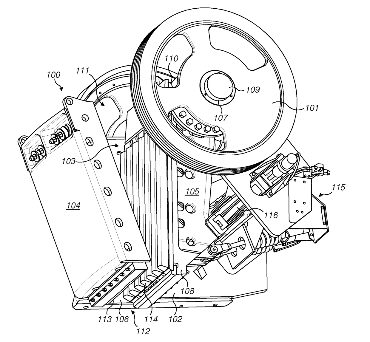
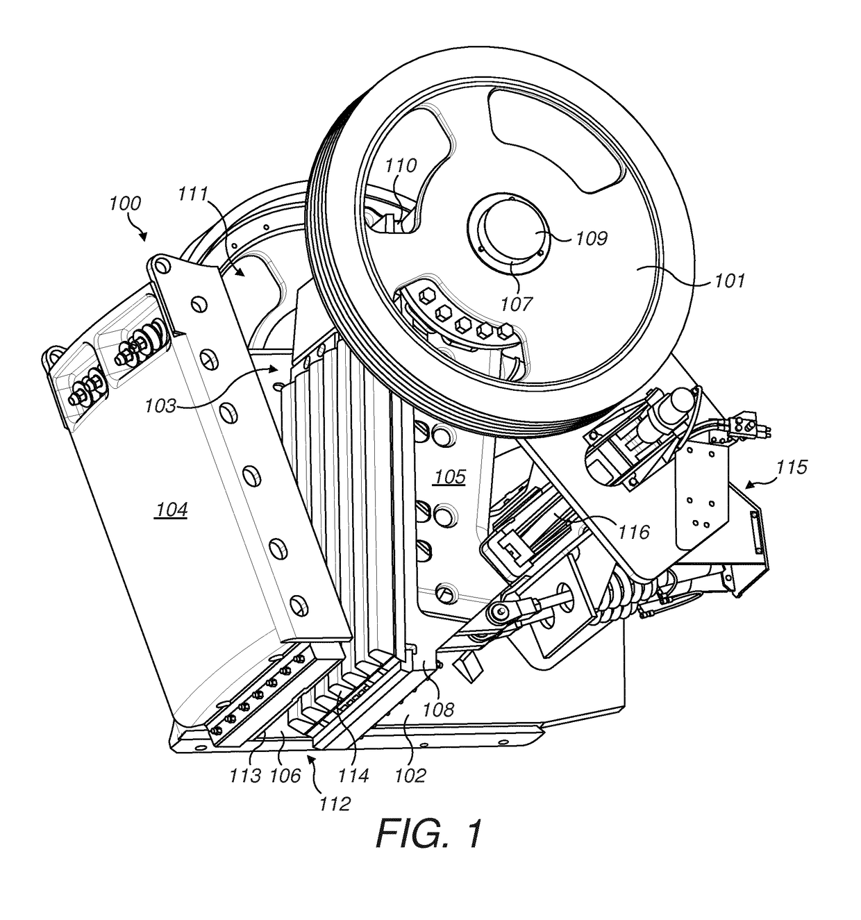
[0026]Referring to FIG. 1, a jaw crusher 100 comprises a main frame 102 upon which is mounted a movable jaw 105 and a substantially fixed jaw 104. Movable jaw 105 is mounted eccentrically at a rotatable shaft 107 (covered at its respective ends by a pair of end caps 109) and is positioned separated and opposed to fixed jaw 104. The orientation of fixed jaw 104 and movable jaw 105 relative to one another is convergent along their respective lengths such that a separation distance between fixed jaw 104 and movable jaw 105 decreases in the downward lengthwise direction. A crushing plate 113 is removably attached to fixed jaw 104 and a corresponding crushing plate 114 is removably attached to movable jaw 105 with the region between the opposed plates 113, 114 representing a crushing zone 103. Main frame 102 comprises two opposed frame walls that support the front frame end and extend either side of fixed jaw 104 and movable jaw 105 to further define the crushing zone 103. The opposed fi...


PUM


Abstract

A mounting assembly arranged to mount a jaw at a jaw crusher includes a rotatable shaft having a jaw bearing mount region that is eccentric relative to a longitudinal axis of the shaft. A central axis of a jaw bearing that mounts the jaw at the crusher is off-set from a central axis of a frame bearing that mounts the shaft at the crusher by a distance in the range of 20 mm to 35 mm.

Description

FIELD OF INVENTION[0001]The present invention relates to a crushing jaw mounting assembly for mounting a movable jaw at a jaw crusher having an optimised eccentric throw for maximising crusher capacity.BACKGROUND ART[0002]Jaw crushers typically comprise a fixed jaw and a movable jaw that together define a crushing zone. A drive mechanism is operative to rock the movable jaw back and forth in order to crush material within this zone. The crushing zone is generally convergent towards its lower discharge end so that crushable material, fed to an upper and wider end of the zone, is capable of falling downward under gravity whilst being subject to repeated cycles of crushing movement in response to the cyclical motion of the movable jaw. The crushed material is then discharged under gravity through the lower and narrower discharge end onto a conveyor for onward processing or a stockpiling.[0003]Example jaw crushers in which a movable jaw oscillates back and forth relative to a stationary...

Claims


Application Information

Patent Timeline
Patent Type & Authority Applications(United States)
IPC IPC(8): B02C1/04B02C1/10
CPCB02C1/04B02C1/10B02C1/02
Inventor SVENSSON, JOHANSVENSSON, ARVIDSVEDENSTEN, PER
Owner SANDVIK INTELLECTUAL PROPERTY AB
Why Eureka
Try Eureka