
Multi-hop intelligent relaying method and apparatus for use in a frequency division duplexing based wireless access network

Inactive Publication Date: 2007-05-15
RPX CLEARINGHOUSE
View PDF3 Cites 74 Cited by
  • Summary
  • Abstract
  • Description
  • Claims
  • Application Information

AI Technical Summary

Benefits of technology

[0014]The present invention provides a multi-hop relaying method and apparatus for use in a cellular network that will substantially eliminate“coverage holes” within network cells, while also making the best use of the frequency spectrum so as to improve capacity. The apparatus according to the present invention is in the form of an intelligent relay. An important novel aspect of the present invention is that fixed intelligent relays utilized as multi-hop extensions within the FDD macro-cell would deliver higher coverage with minimal changes to the BS and the user equipment (UE)—i.e., cellular terminals, mobile PDAs, . . . etc.
[0024]Further, with intelligent use of the BS and intelligent relays in conjunction with the quality of service (QoS) needs of the data to be transmitted,—i.e., by selecting either a direct BS-UE connection (e.g., low rate, low delay services) or a multi-hop intelligent relay connection (e.g., best effort services) as appropriate—it is apparent that the system functionality can be optimized. In addition to such QoS enabled routing, another beneficial aspect of the present invention includes interference reduction.

Problems solved by technology

Also, such systems employ aggressive frequency reuse, since they attempt to maximize the peak rates to the favourable users and provide lower rates at the cell edge where the interference is worst.
A fundamental problem raised by this model is the issue of interference generated by the transmissions from the relays.
This problem limits the realizable capacity while improving coverage.
Simultaneous transmission on these two hops is not possible unless some interference management strategy is employed.

Method used


Image

  • Multi-hop intelligent relaying method and apparatus for use in a frequency division duplexing based wireless access network
  • Multi-hop intelligent relaying method and apparatus for use in a frequency division duplexing based wireless access network
  • Multi-hop intelligent relaying method and apparatus for use in a frequency division duplexing based wireless access network

Examples


Embodiment Construction

[0035]The invention will be described for the purposes of illustration only in connection with certain embodiments; however, it is to be understood that other objects and advantages of the present invention will be made apparent by the following description of the drawings according to the present invention. While a preferred embodiment is disclosed, this is not intended to be limiting. Rather, the general principles set forth herein are considered to be merely illustrative of the scope of the present invention and it is to be further understood that numerous changes may be made without straying from the scope of the present invention.

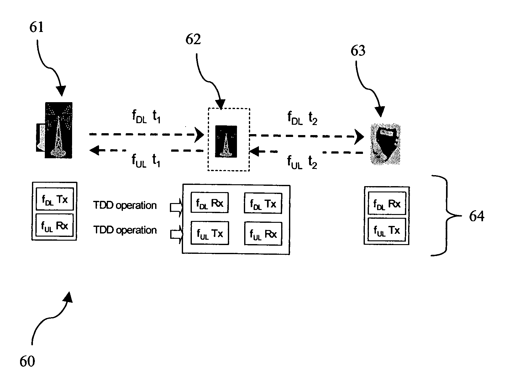
[0036]With reference to FIG. 6, a schematic is shown indicating a BS 61, a UE element 63, and an intelligent relay 62 in accordance with the present invention located between the BS and UE element. In this fixed relaying configuration 60, for the FDD mode, hopping operation 64 is done through intelligent relays. While this would suggest an increase of ...


PUM


Abstract

A multi-hop relaying method and apparatus used in a cellular network. The multi-hop transmission scheme utilizes intelligent relays within a conventional cellular system having at least one base station, one or more intelligent relays, and user equipment elements. The method includes selecting the strongest pilot signal from among the base stations and intelligent relays, reporting such to the base station, distributing an active user list to the relays along with scheduling and routing information via a relay control channel, and transmitting data according to a respective active user based upon the pilot signal strength to maximize coverage and capacity over the cellular system.

Description

RELATED APPLICATIONS[0001]The present application claims priority from U.S. Provisional Application Ser. No. 60 / 458,374 filed Mar. 31, 2003.BACKGROUND OF THE INVENTION[0002]1. Field of the Invention[0003]The present invention relates to the field of relaying within a frequency division duplexing (FDD) based cellular communications network designed for packet transmission. More specifically, the present invention is a method and apparatus involving a multi-hop transmission scheme utilizing intelligent relays to maximize coverage and capacity over a conventional cellular system designed for packet transmission.[0004]2. Description of the Prior Art[0005]Multi-hop relaying and ad-hoc networks are emerging as popular options to enhance the coverage performance of packet-based wireless networks. The basic idea of such networks is that the users in locations with poor wireless environments get their data from nearby wireless entities in the same cell, such as peer mobiles, moving vehicular...

Claims


Application Information

Patent Timeline
IPC IPC(8): H04B7/185H04B7/005H04B7/15
CPCH04B7/155H04W52/46
Inventor PERIYALWAR, SHALINICHEONG, YOON CHAESENARATH, NIMAL
Owner RPX CLEARINGHOUSE
Learn More