
Lighthouse lantern for lighthouse using laser diode and fluorescent substance

a technology of laser diodes and lighthouses, applied in special-purpose vessels, lighting applications, lighting and heating apparatuses, etc., can solve the problems of frequent inspection and maintenance of electric power units, narrow light emitting area of led light radiated to the outside, and inefficient use of electric power, etc., to suppress frequent failures, improve power efficiency, and high output

Active Publication Date: 2018-10-25
PUKYONG NAT UNIV IND ACADEMIC COOPERATION FOUND
View PDF4 Cites 1 Cited by
  • Summary
  • Abstract
  • Description
  • Claims
  • Application Information

AI Technical Summary

Benefits of technology

The present disclosure aims to provide a lighthouse lantern that can generate high output with low input power, leading to improved power efficiency. Additionally, it can suppress failures that frequently occur near sea or seawater, and also reduce production costs.

Problems solved by technology

Therefore, when the incandescent bulb which is currently in operation fails, the motor mounted in the bulb exchanger is driven such that the problematic bulb is automatically replaced with a spare bulb.
However, in such a bulb type lighthouse lantern, inefficient use of electric power requires frequent inspection and maintenance of an electric power unit.
Due to the shortened durability of the battery, frequent inspections of a manager are required.
However, when the stack of these LED modules is used, the light emitting area of the light radiated from the LED to the outside is narrowed due to the cover plate pressing the lens portion of the LED module upward and downward.
There is a problem that the luminous intensity in such a portion is relatively lower than that of the lens portion of the LED module and the overall brightness of the lighthouse lantern is lowered.
In this regard, in the case of a conventional lighthouse lantern using LED, a failure frequently occurs due to the corrosion of the LED module.

Method used


Image

  • Lighthouse lantern for lighthouse using laser diode and fluorescent substance
  • Lighthouse lantern for lighthouse using laser diode and fluorescent substance
  • Lighthouse lantern for lighthouse using laser diode and fluorescent substance

Examples


Embodiment Construction

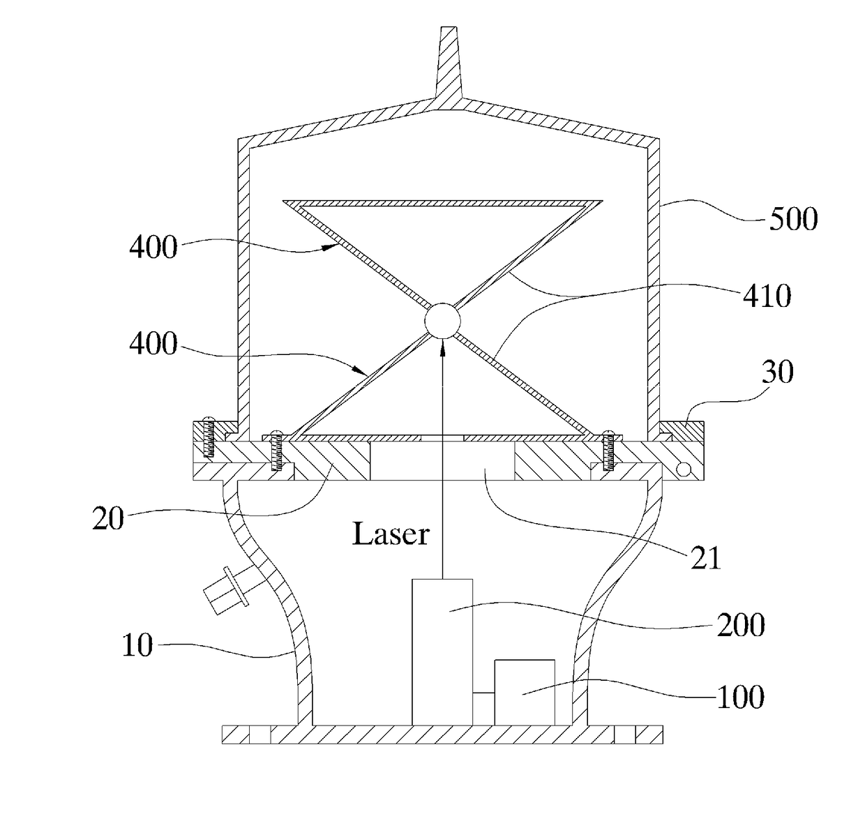
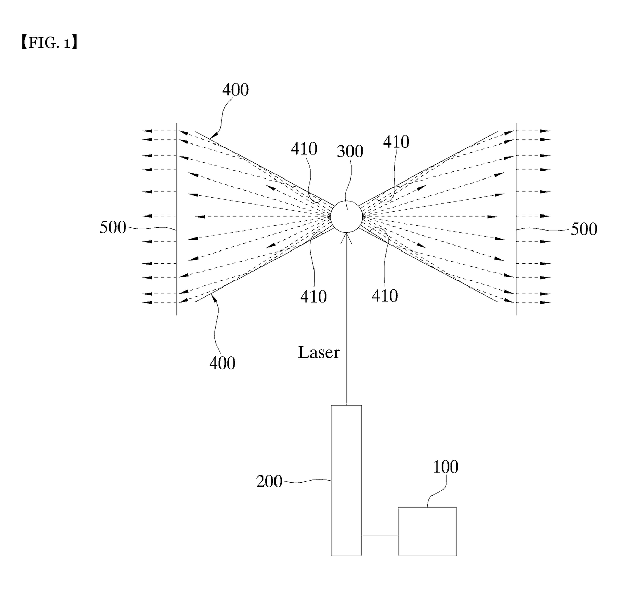
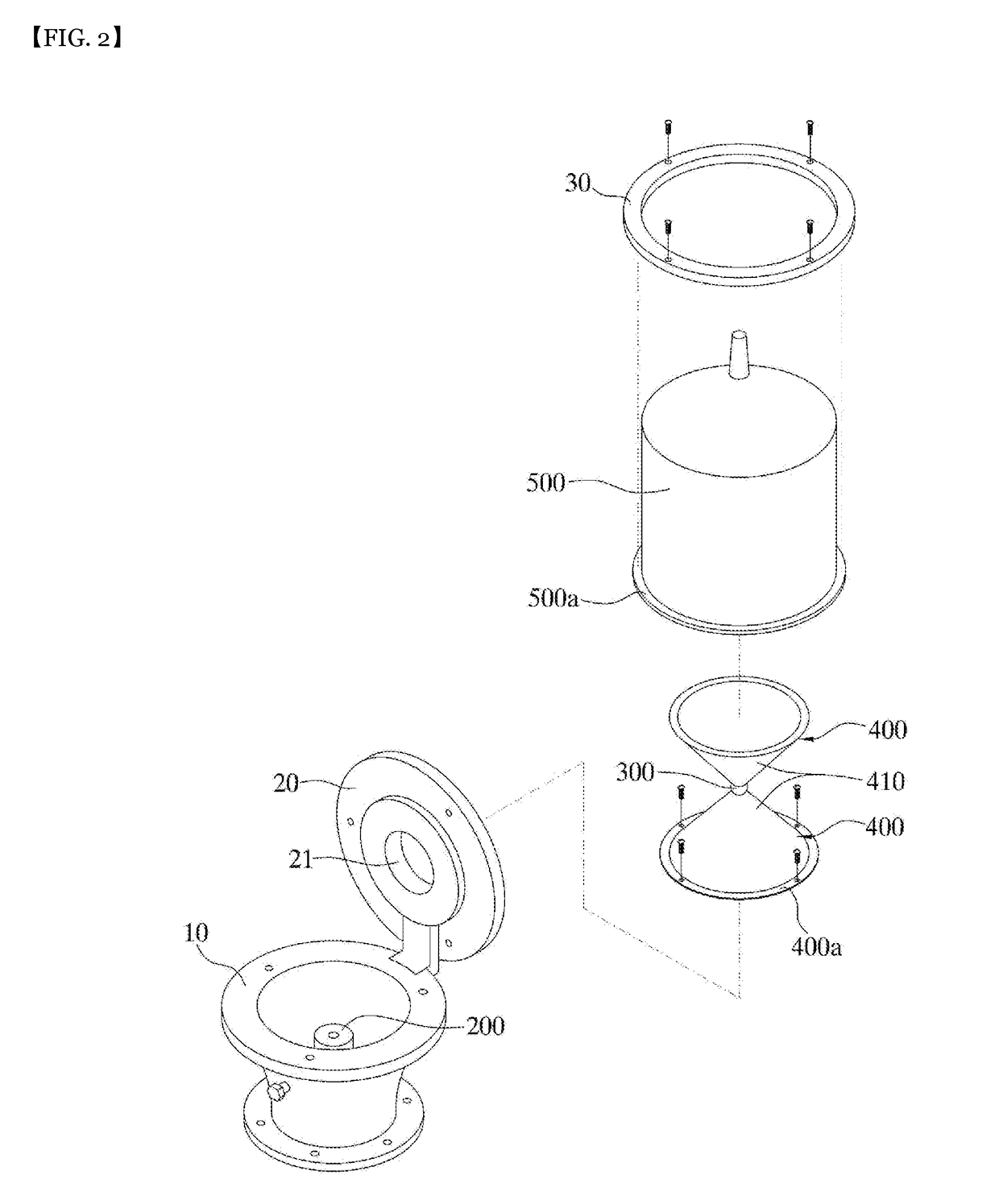
[0015]Hereinafter, a lighthouse lantern including a laser diode and a phosphor-containing emitter according to an embodiment of the present disclosure will be described in detail with reference to the accompanying drawings. Examples of various embodiments are illustrated and described further below. It will be understood that the description herein is not intended to limit the claims to the specific embodiments described. On the contrary, it is intended to cover alternatives, modifications, and equivalents as may be included within the spirit and scope of the present disclosure as defined by the appended claims. For simplicity and clarity of illustration, elements in the figures are not necessarily drawn to scale. The same reference numbers in different figures denote the same or similar elements, and as such perform similar functionality.

[0016]It will be understood that, although the terms “first”, “second”, “third”, and so on may be used herein to describe various elements, compon...


PUM


Abstract

A lighthouse lantern comprising a power supply and a phosphor-containing emitter is disclosed. The lighthouse lantern includes a power supply; a laser diode configured for receiving power from the power supply and irradiating laser in one direction; a phosphor-containing emitter positioned on a traveling line of the laser, wherein the emitter is configured for receiving the laser and emitting light; and a pair of reflective structures disposed symmetrically with respect to the phosphor-containing emitter, wherein each reflective structure has a reflective surface inclined in a direction away from the phosphor-containing emitter, wherein the reflective surfaces of the reflective structures are symmetrical with each other with respect to the phosphor-containing emitter. In accordance with the present disclosure, the lighthouse lantern may generate high output with low input power and thus has improved power efficiency, may suppress frequent failures near sea or seawater, and may reduce production costs.

Description

TECHNICAL FIELD[0001]The present disclosure relates to a lighthouse lantern, and more specifically, to a lighthouse lantern with production of high output at low input power.RELATED ART[0002]In a lighthouse lantern using a conventional incandescent lamp, a plurality of incandescent lamps are installed in a mechanical structure called a bulb exchanger. Therefore, when the incandescent bulb which is currently in operation fails, the motor mounted in the bulb exchanger is driven such that the problematic bulb is automatically replaced with a spare bulb.[0003]However, in such a bulb type lighthouse lantern, inefficient use of electric power requires frequent inspection and maintenance of an electric power unit. Due to the shortened durability of the battery, frequent inspections of a manager are required.[0004]Accordingly, recently, a lighthouse lantern using an LED having a higher luminance than an incandescent lamp has been developed and used. In such an LED-based lighthouse lantern, ...

Claims


Application Information

Patent Timeline
IPC IPC(8): B63B22/16B63B51/00F21K9/60F21V23/02F21V5/04F21V7/04
CPCB63B22/16B63B51/00F21K9/60F21V23/02F21V5/04F21V7/04F21V7/0025F21V7/041F21W2111/00F21Y2101/00F21V9/30B63B22/166B63B2201/08F21V5/045F21W2111/04F21K9/69F21Y2115/00F21Y2115/30
Inventor YANG, HYUN KYOUNG
Owner PUKYONG NAT UNIV IND ACADEMIC COOPERATION FOUND
Learn More