Connector

a technology of connecting rods and connectors, applied in the direction of rod connections, motors, couplings, etc., can solve the problems of no mechanism for removing the connection device, associated cost and risk, and the destruction of the device, so as to reduce the chance of accidental movement

Pending Publication Date: 2018-10-25
BALLTEC
View PDF0 Cites 4 Cited by
  • Summary
  • Abstract
  • Description
  • Claims
  • Application Information

AI Technical Summary

Benefits of technology

[0006]Provision of locking elements which move between the engaged and disengaged position based on the movement of a cage, allows for manipulation of the cages to move the locking elements between locked and unlocked positions. Accordingly, retraction of the cages can move the locking elements to the disengaged position so as to allow disconnection of the connector without the use of divers, or destruction of the device.
[0007]The ramp surfaces may comprise a transition surface from a lower region, where the locking elements lie in the disengaged position to an upper region where the elements lie in the engaged position. The upper region and / or the lower region may be ramped, alternatively, the upper region and / or the lower region may be flat surfaces, parallel to the cages. As a further alternative, the upper region and / or the lower region may be formed as depressions. Forming the upper region in particular as a flat surface, or especially as a depression reduces the chances of accidental movement from the engaged position to the disengaged position.
[0041]The provision of a sleeve over the movable cages prevents resistance between the cages and an aperture (or the like) that the connector is engaging with from acting against the movement of the cages to the engaged position.
[0046]This provision of an additional “detach” position, allows for permanent detachment without movement back to the disengaged position, which can be more easily achieved, for example by use of a pull-in and / or retraction head, rather than an ROV

Problems solved by technology

Whilst installation of the device of WO2010 / 038056 is easy, there is no mechanism for removing the connection device, as may be required for disassembly / maintenance.
Disconnection would require divers (with the associated cost and risk) and destruction of the device.

Method used


Image

  • Connector
  • Connector
  • Connector

Examples


first embodiment

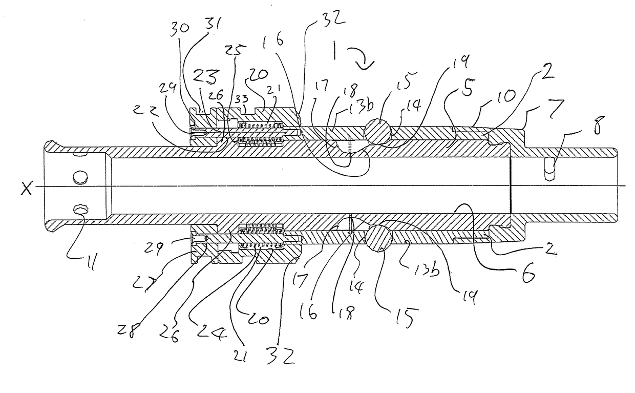
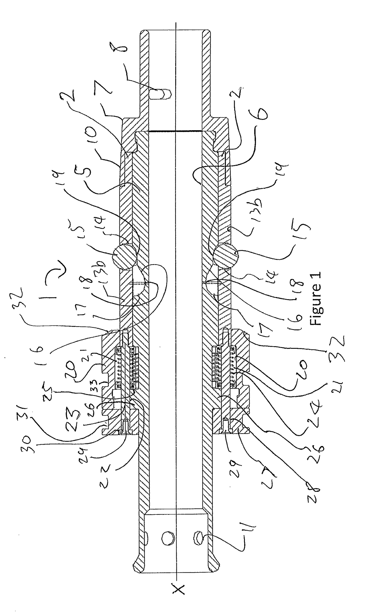
[0064]FIG. 1 is a lateral cross section through a connector according to the invention;

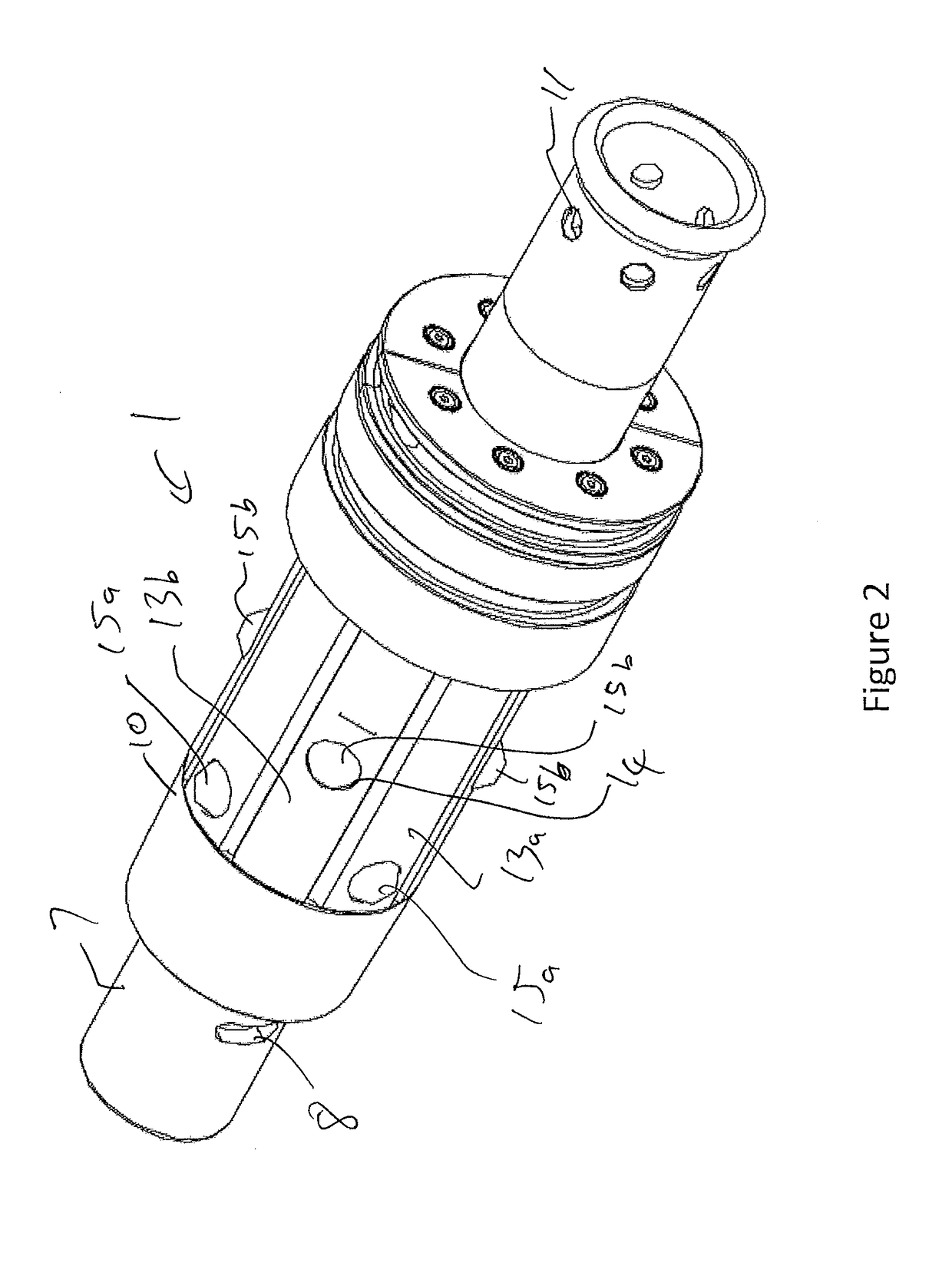
[0065]FIG. 2 is a rear isometric view of the connector of FIG. 1;

[0066]FIG. 3 is a front isometric view of the connector of FIGS. 1 and 2;

[0067]FIG. 4 is a rear isometric view of the connector of FIGS. 1 to 3 inserted into the aperture of a support pillar, the latter shown part-cutaway;

[0068]FIG. 5 is a front isometric view of the connector of FIGS. 1 to 3 inserted into the aperture of a support pillar, the latter shown part-cutaway;

[0069]FIG. 6 is a front isometric view of the connector of FIGS. 1 to 3 attached to a bend restrictor at the front and a bend stiffener at the rear and inserted into the aperture of a support pillar, the latter shown part-cutaway;

[0070]FIG. 7 is a rear isometric view of the connector of FIGS. 1 to 3 attached to a bend restrictor at the front and a bend stiffener at the rear and inserted into the aperture of a support pillar, the latter shown part-cutaway;

[0071]FIG. 8 i...

second embodiment

[0076]FIG. 13 is an section through a connector according to the invention with locking elements in the engaged position, the section is towards line A-A in FIG. 17, such that the top half of the drawing is taken along an angle offset by 45 degrees to the bottom half of the drawing;

[0077]FIG. 14 is a section through the connector of FIG. 13, taken along the same angles and with the locking elements in the disengaged position;

[0078]FIG. 15 is a section through the connector of FIGS. 13 and 14 taken along the same angles and with some locking elements in the engaged position and others in the disengaged position;

[0079]FIG. 16 is a section through the connector of FIGS. 13 to 15 taken along the same angles and with the locking elements in a detached position;

[0080]FIG. 17 is a rear isometric view of the connector of FIGS. 13 to 16 with the locking elements in the engaged position;

[0081]FIG. 18 is a front isometric view of the connector of FIGS. 13 to 16 with the locking elements in the...


PUM


Abstract

An elongate connector for subsea connection of cables and the like to wind turbine generators has a plurality of locking elements arranged on ramp surfaces and held in a plurality of cages on the connector. The cages are moveable to move the locking elements along the ramp surfaces between an engaged position and a disengaged position and the plurality of cages are moveable independently of each other. A release collar is provided, which can move all the cages simultaneously to the disengaged position, in order to allow removal of the connector.

Description

TECHNICAL FIELD OF THE INVENTION[0001]The present invention relates to connectors, in particular subsea connectors and especially subsea connectors for connecting cables to power generation apparatus, such as offshore wind turbines. The invention also relates to methods of connection and removal of such connectors.BACKGROUND TO THE INVENTION[0002]Power is collected from offshore wind driven turbine generators by electric cables. The cables are connected at one end to a support pillar of the generator, and pass through an aperture in the wall of the support pillar or “pile” out to the sea bed. The cables tend to pass through the (substantially vertical) wall of the pile at an oblique angle. An exemplary connector for connecting cables to wind turbines is disclosed in WO2010 / 038056, which has a series of wedge-shaped latches, which latch onto the oblique inside edge of the aperture through the support pillar. In the arrangement of WO2010 / 038056, the latches are resiliently biased outw...

Claims


Application Information

Patent Timeline
Patent Type & Authority Applications(United States)
IPC IPC(8): F16B7/04H02G9/12
CPCF16B7/042H02G9/12F16L1/20H02G1/10H02G9/02F03D80/00F16B2/16F16B7/1409F03D1/00Y02E10/72F16L1/123F16L5/00F16L37/23H02G9/025
Inventor PRESTON, JONATHAN SCOTTPARRY, WILLIAM DAVID LOTONO'CONNOR, DANIEL
Owner BALLTEC
Why Eureka
Try Eureka