Control device for machine tool performing oscillation cutting

a technology of control device and machine tool, which is applied in the direction of electric programme control, program control, instruments, etc., can solve the problems of not being able to solve the problem that the cutting tool exceeds the cut may occur in the workpiece near the machining stop position, and the amplitude does not immediately comply and diminish, so as to achieve the effect of improving compliance and facilitating complian

Active Publication Date: 2018-10-25
FANUC LTD
View PDF0 Cites 3 Cited by
  • Summary
  • Abstract
  • Description
  • Claims
  • Application Information

AI Technical Summary

Benefits of technology

[0007]In the first aspect, the resultant command is normalized using a representative value, for example, the position command, is input into the learning control part, and the output from the learning control part is denormalized using a representative value, for example, the position command. Thus, even when the representative value at the time of inputting to the learning control part is different from the representative value at the time of outputting, since the resultant command is denormalized using the representative value at the time of output, the change in the representative value, for example, the position command, can easily be complied with. Therefore, even when learning control is applied, compliance can be improved.

Problems solved by technology

However, when learning control is applied to intermittent cutting, even if the amplitude of the oscillating motion is decreased near the machining stop position, the amplitude does not immediately comply and diminish.
Therefore, the problem that the cutting tool exceeds the machining stop position may not be solved in some cases.
Furthermore, depending on the shape of workpiece, there is a risk that a cut may occur in the workpiece near the machining stop position.

Method used


Image

  • Control device for machine tool performing oscillation cutting
  • Control device for machine tool performing oscillation cutting
  • Control device for machine tool performing oscillation cutting

Examples


first embodiment

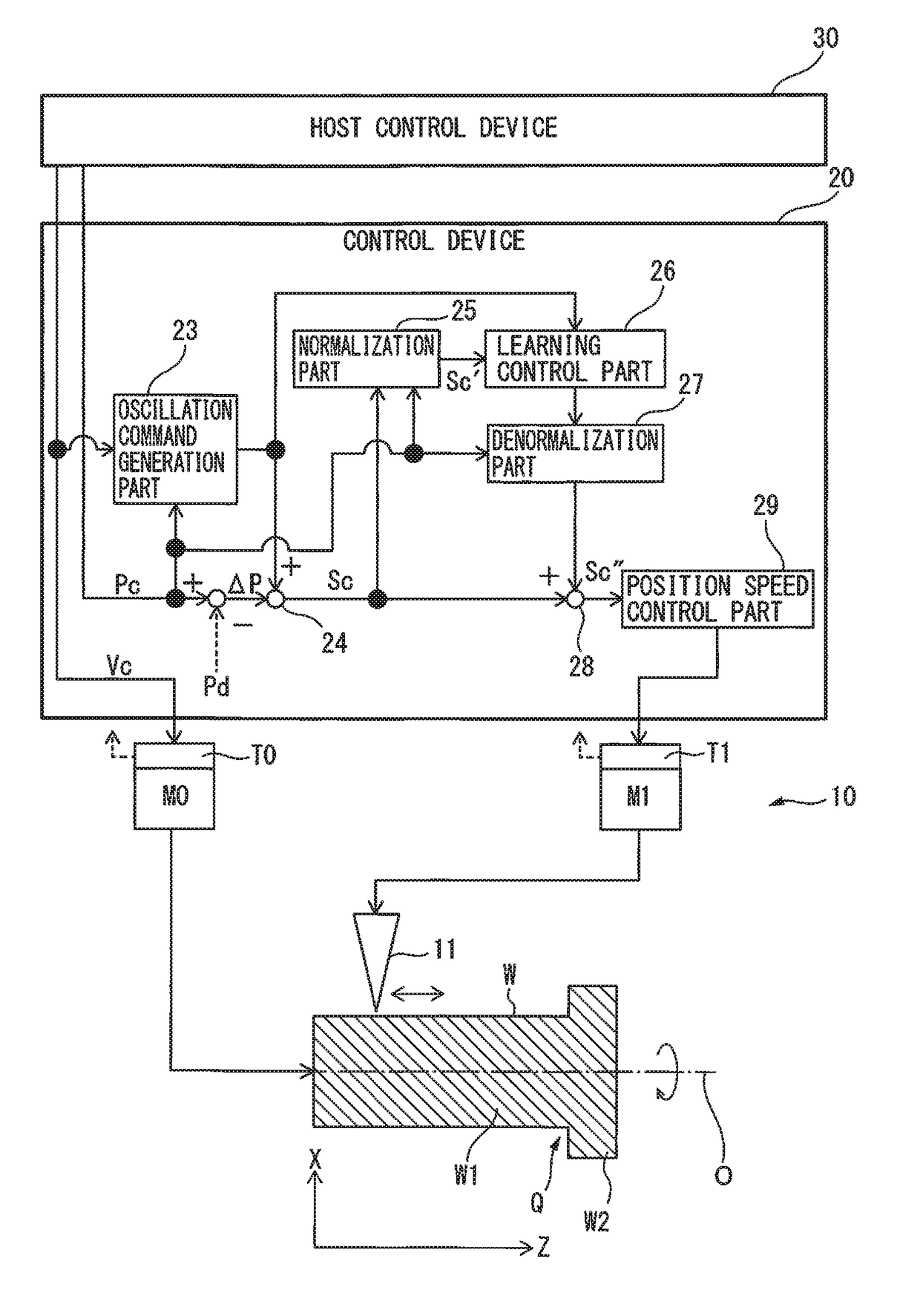
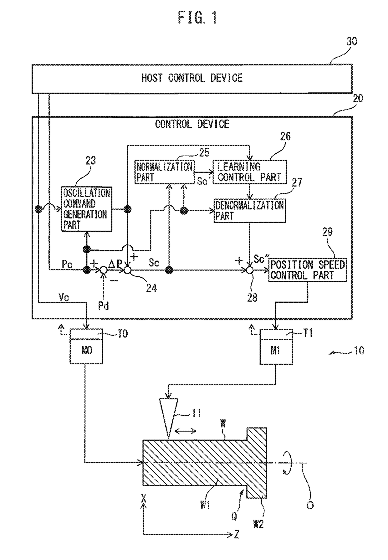
[0020]FIG. 1 is a drawing of a system including a control device according to a As shown in FIG. 1, the system 1 includes a machine tool 10, a control device 20 for controlling the machine tool 10, and a host control device 30 connected to the control device 20. The machine tool 10 includes a tool 11, and the tool 11 cuts the outer peripheral surface or the inner peripheral surface of a workpiece W, which is at least partially rotationally symmetrical about the axis of rotation O. Furthermore, in FIG. 1, etc., the axis of rotation of the workpiece W is designated as the Z axis, and the axis perpendicular to the Z axis is designated as the X axis.

[0021]The spindle M0 of the machine tool 10 rotates the workpiece W around the axis of rotation O thereof. Further, the fees axis M1 of the machine tool 10 moves the tool 11 along the generatrix of the workpiece W. Note that, as will be described later, two or more feed axes M1 and M2 may move the tool 11 along the generatrix of the workpie...

second embodiment

[0035]First, in step S11 of FIG. 3, the oscillation command generation part 23 generates an oscillation command for the fees axis M1 based on the position command Pc and the spindle rotation speed command Vc provided from the host control device 30. In the example shown in FIG. 1, an oscillation command for only the fees axis M1 is generated, since the tool 11 oscillates only along a linear line parallel to the axis of rotation O. FIG. 4 is a drawing of another system including a control device according to a In the example shown in FIG. 4, the tapered portion W3 is coupled to the flange W2. In such a case, the tool 11 oscillates obliquely along the generatrix of the tapered portion W3 to cut the outer peripheral surface of the tapered portion W3. Since the tool 11 moves in a resultant direction of the X direction and the Z direction, in order to move the tool 11, two feed axes M1 and M2 are required. In such a case, in step S11, oscillation commands for the two feed axes M1 and M2...


PUM


Abstract

A control device for a machine tool includes an oscillation command generation part which generates an oscillation command for a fees axis, a first adding part which adds an oscillation command to a position deviation between a position command and the detected position of the fees axis to generate a resultant command, a normalization part for normalizing the resultant command, a learning control part that obtains a correction amount of the resultant command based on an oscillation phase obtained from the oscillation command and a normalized resultant command and which adds the correction amount to the resultant command, a denormalization part which denormalizes an output from the learning control part, and a second adding part for adding a denormalized output from the denormalization part to the resultant command.

Description

1. FIELD OF THE INVENTION[0001]The present invention relates to a control device for a machine tool performing oscillation cutting.2. DESCRIPTION OF THE RELATED ART[0002]When swarf is continuously generated during the machining of a workpiece using the cutting tool of a machine tool, the swarf may become entangled with the cutting tool. Thus, a technology of oscillating the tool so as to intermittently cut the workpiece is known (refer to, for example, Japanese Patent No. 5033929 or Japanese Patent No. 5139592).[0003]However, Japanese Patent No. 5033929 and Japanese Patent No. 5139592 do not take the termination of cutting at a predetermined machining end position into account. Therefore, a problem occurs in that the cutting tool continues to oscillate and exceeds the predetermined machining end position. In connection thereto, W / O 2016 / 047485 discloses “When the cutting tool reaches a predetermined cutting tool machining stop position on a workpiece in the machining feeding directi...

Claims


Application Information

Patent Timeline
Patent Type & Authority Applications(United States)
IPC IPC(8): G05B19/18
CPCG05B19/182G05B2219/45044G05B2219/31263G05B2219/37372B23Q15/12B23Q15/14
Inventor OHO, YUSAKUYAMAMOTO, KENTA
Owner FANUC LTD
Why Eureka
Try Eureka