Three-dimensional modeling apparatus and three-dimensional modeling method

a three-dimensional modeling and modeling apparatus technology, applied in the direction of additive manufacturing processes, manufacturing tools, applying layer means, etc., can solve the problems of affecting the accuracy of modeling, so as to reduce the size of the entire apparatus, the surface roughness of the three-dimensional object is small, and the height of the apparatus can be reduced.

Active Publication Date: 2018-11-01
SEIKO EPSON CORP
View PDF5 Cites 26 Cited by
  • Summary
  • Abstract
  • Description
  • Claims
  • Application Information

AI Technical Summary

Benefits of technology

[0006](1) According to a first aspect of the invention, a three-dimensional modeling apparatus for producing a three-dimensional object using a thermoplastic material is provided. The three-dimensional modeling apparatus includes a drive motor, a plasticizing section having a flat screw configured to be rotated by the drive motor, the plasticizing section being configured to plasticize and convert the material into a molten material by the rotation of the flat screw, and a nozzle configured to inject the molten material. The three-dimensional modeling apparatus according to this aspect plasticizes a material by using the plasticizing section that includes the flat screw, and thus the height of the apparatus can be reduced and the size of the entire apparatus can be reduced.
[0007](2) In this three-dimensional modeling apparatus, a cross-section of a nozzle hole of the nozzle may have a shape that enables the molten material injected from the nozzle hole to have a cross-section closer to a polygonal shape than a round shape. According to the three-dimensional modeling apparatus, the molten material injected from nozzle hole has a cross section closer to a polygonal shape than a round shape, and thus gaps in the deposited linear molten material can be reduced. Consequently, the surface roughness of the three-dimensional object becomes small and the modeling precision can be increased.
[0008](3) In this three-dimensional modeling apparatus, the cross-section of the nozzle hole may be a substantially quadrangular shape. According to this three-dimensional modeling apparatus, gaps in the deposited linear molten material can be further reduced and thus the surface roughness of the three-dimensional object can be further reduced and the modeling precision can be increased.
[0009](4) In this three-dimensional modeling apparatus, the nozzle may have a plurality of nozzle holes. According to this three-dimensional modeling apparatus, the shape of the molten material injected from the nozzle can be adjusted by the arrangement of the nozzle holes. Consequently, the surface roughness can be reduced and the design of the three-dimensional object can be improved.
[0010](5) In this three-dimensional modeling apparatus, the nozzle holes may be arranged in a matrix. According to this three-dimensional modeling apparatus, the nozzle holes arranged in the matrix enables the molten material injected from the nozzle to have an entire cross section close to a quadrangular shape, and thus the surface roughness can be further reduced.
[0011](6) In this three-dimensional modeling apparatus, the nozzle may be placed so as to form a gap 1.1 times or more and 1.5 times or less than a hole diameter of the nozzle hole of the nozzle between an upper surface of the three-dimensional object being produced and a tip of the nozzle. According to this three-dimensional modeling apparatus, the molten material injected from the tip of the nozzle is deposited on the upper surface of the three-dimensional object in a free state in which the molten material is not pressed against the upper surface of the three-dimensional object being produced. Accordingly, the molten material injected from the nozzle can be deposited while maintaining its cross-sectional shape, and thus the surface roughness of the three-dimensional object can be reduced. As a result, the surface roughness of the three-dimensional object can be further reduced.

Problems solved by technology

The above-described known technique extrudes the molten material by the rotation of the elongated screw, and thus the height of the entire apparatus becomes considerably large and downsizing of the apparatus has been hindered.
Furthermore, due to lots of gaps in the objects produced by laminating the material extruded from the nozzle, their modeling precision is low, and it is necessary to use solvent to increase the modeling precision.

Method used


Image

  • Three-dimensional modeling apparatus and three-dimensional modeling method
  • Three-dimensional modeling apparatus and three-dimensional modeling method
  • Three-dimensional modeling apparatus and three-dimensional modeling method

Examples


modification 1

[0063]The present invention is not limited to the above-described examples and embodiments, and various modifications can be made without departing from the scope of the invention. For example, the following modifications may be provided.[0064]Modification 1

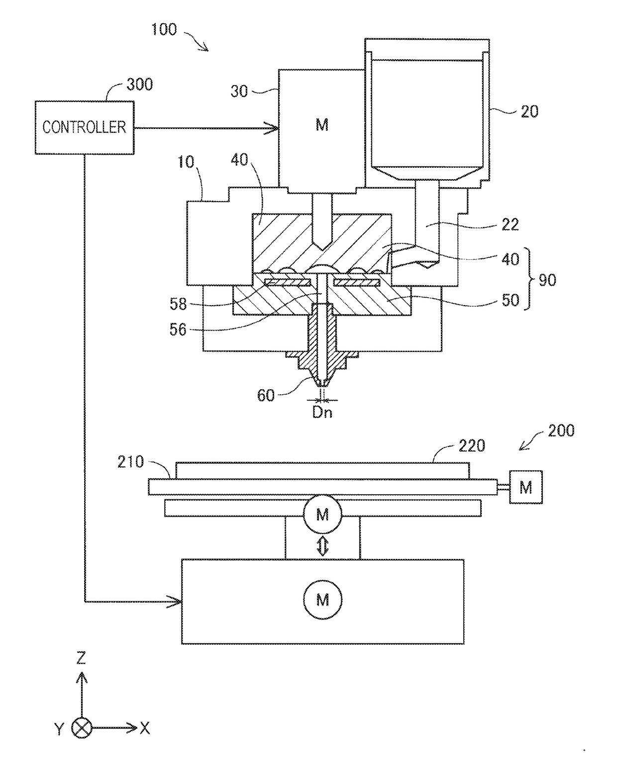
[0065]In the above-described embodiments, the three-dimensional modeling apparatuses include the hopper 20; however, the hopper 20 may be omitted.

[0066]The present invention is not limited to the above-described embodiments and modification, and various structures can be provided without departing from the scope of the invention. For example, technical features in the embodiments, examples, and modifications corresponding to the technical features in each embodiment described in SUMMARY may be replaced or combined to solve some or all of the above problems or to achieve some or all of the above-described effects. Unless the technical features are described as essential in this specification, the technical features may be omitted ...


PUM

PropertyMeasurementUnit
temperatureaaaaaaaaaa
glass transition pointaaaaaaaaaa
diametersaaaaaaaaaa

Abstract

A three-dimensional modeling apparatus includes a drive motor, a plasticizing section having a flat screw configured to be rotated by the drive motor, the plasticizing section being configured to plasticize and convert the material into a molten material by the rotation of the flat screw, and a nozzle configured to inject the molten material.

Description

[0001]This application claims priority under 35 U.S.C. § 119 to Japanese Patent Application No. 2017-089248 filed on Apr. 28, 2017, the entire disclosure of which is expressly incorporated by reference herein.BACKGROUND1. Technical Field[0002]The present invention relates to a three-dimensional modeling technique that uses a thermoplastic.2. Related Art[0003]JP-A-2006-192710 describes an extrusion-deposition-lamination modeling apparatus that uses a molten resin. This apparatus melts a wire-like thermoplastic material by using a preheater and extrudes the molten material from an extrusion nozzle by using the rotation of an elongated screw to produce a three-dimensional object. Since such three-dimensional objects produced by extrusion have many gaps and the degree of filling is low, solvent is supplied to the cured material to dissolve the cured material to reduce the gaps in the three-dimensional objects.[0004]The above-described known technique extrudes the molten material by the ...

Claims


Application Information

Patent Timeline
Patent Type & Authority Applications(United States)
IPC IPC(8): B29C64/209B29C64/40B29C64/295B29C64/106B29C64/241
CPCB29C64/209B29C64/40B29C64/295B29C64/106B29C64/241B33Y10/00B33Y30/00B33Y70/00B33Y40/00B33Y50/02B29C64/307B29C64/118B29C64/20B29C64/393
Inventor SAITO, KOICHIMIZUKAMI, SHUNSUKENAKAMURA, KAZUHIDE
Owner SEIKO EPSON CORP
Why Eureka
Try Eureka