Water Assisted Toilet Plunger

a technology of assisted toilets and plungers, which is applied in water installations, domestic plumbing, construction, etc., can solve the problems of the shut-off valve moving away from the seat, and achieve the effect of quick and simple improvemen

Inactive Publication Date: 2018-11-01
WESBY SCOTT MATTHEW
View PDF3 Cites 0 Cited by
  • Summary
  • Abstract
  • Description
  • Claims
  • Application Information

AI Technical Summary

Benefits of technology

[0006]The usefulness of the disclosure is readily apparent: a single plunger containing the improvement can now be used instead of having two or more plungers each having beneficial features; the use of the existing water in a clogged toilet for the inclusion of hydraulic force for obstruction removal instead of the cumbersome import of an external water source for this purpose. In addition, the quick, simple application of the improvement is evident—the plunger is immersed in a toilet bowl partially or completely filled with water as a result of a clog and positioned onto the trap opening, the operator depresses the button until air bubble cease to exit from the shaft of the plunger, and the plunger is ready for the downward thrust used to expel the obstruction.

Problems solved by technology

Venting occurs when the operator depresses the button, which causes the rod to move longitudinally within the shaft, resulting in the shut off valve moving away from its seat.

Method used


Image

  • Water Assisted Toilet Plunger
  • Water Assisted Toilet Plunger
  • Water Assisted Toilet Plunger

Examples


Embodiment Construction

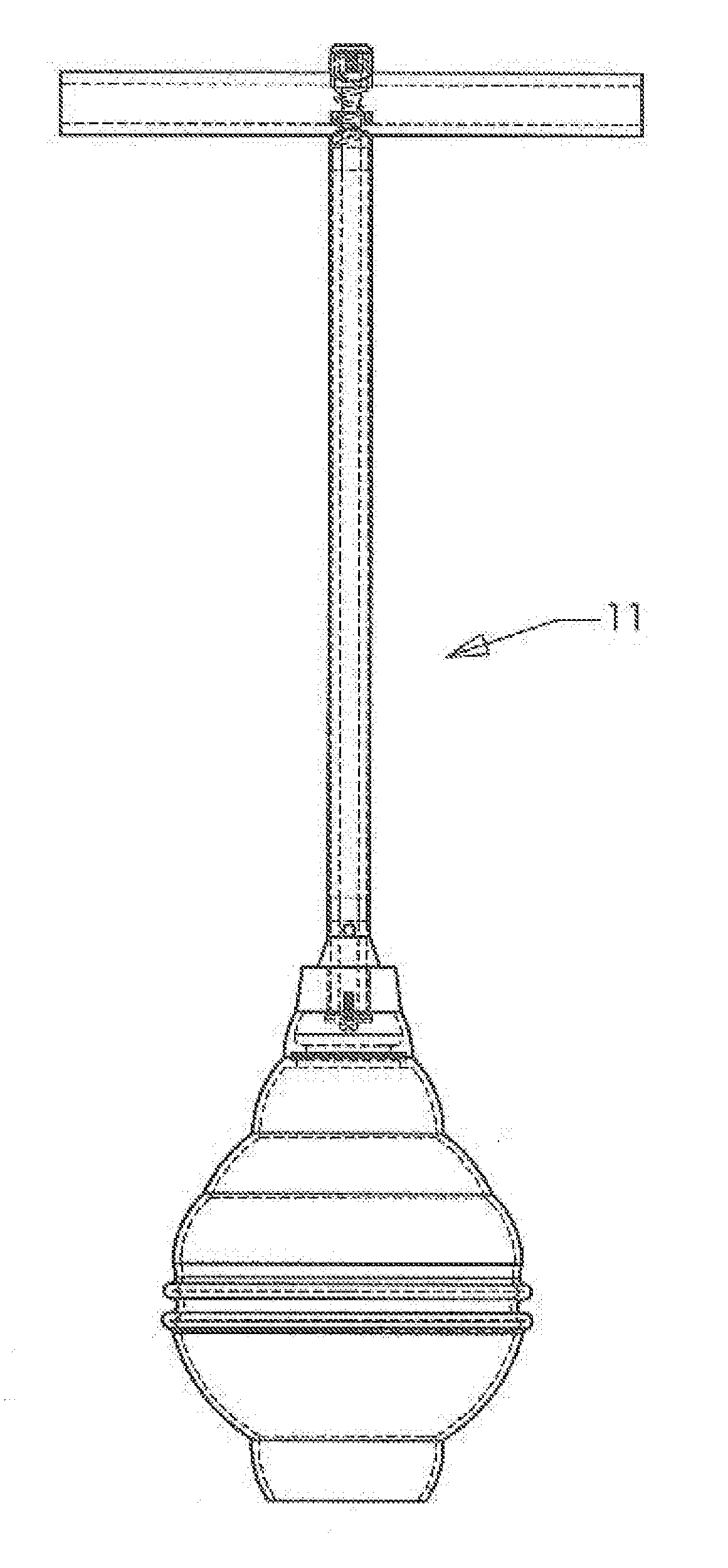
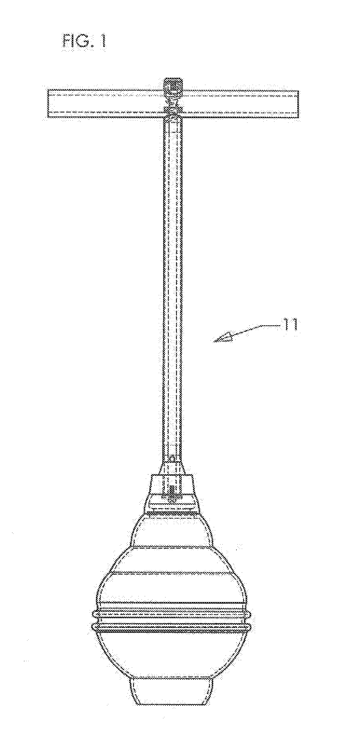
[0016]Referencing the drawings, in particular, FIGS. 2 through 8, an improvement to a typical / conventional toilet plunger (such plunger designed generally by the reference numeral 11 (in the drawings), is embodied in the concepts and principles of an embodiment of the disclosure, and will be described.

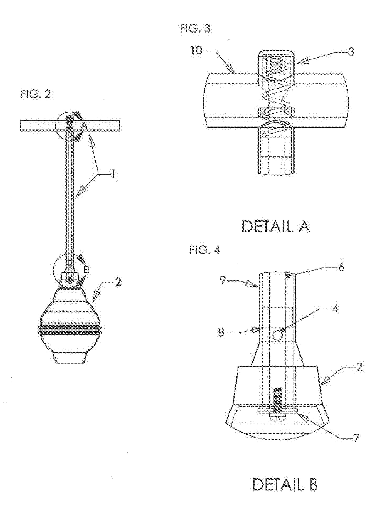
[0017]FIG. 2 illustrates a typical / conventional toilet plunger 11 with a handle / shaft assembly 1 and in this representation, a bellows 2, attached to the handle / shaft assembly 1. FIG. 2 also shows the two principle areas circled where the improvement is located: at the handle 10 and the opposite end of the hollow shaft 9 from the handle 10. FIG. 3 shows a depressible button 3 protruding out the top of a concentric hole in the handle 10. FIG. 4 shows the vent 4, two circular holes in the shaft 9, directly across from each other, located below the lower of two bearings 8 attached to the inside diameter of the hollow shaft 9 as the plunger 11 is situated in a vertical position as is shown...


PUM


Abstract

A typical toilet plunger is disclosed that allows the operator to optionally choose to manually vent a plunger's cup of the air that is naturally trapped within the cup that renders the plunger less efficient as a result of the compressibility of air. The venting of air is accomplished by the opening of a shut off valve located within the inside and top of the cup. The shut off valve is connected to a longitudinal rod supported within the hollow shaft of said plunger. The rod protrudes through the grab handle of the plunger and terminates at a depressible button attached to the rod. Venting occurs when the operator depresses the button, which causes the rod to move longitudinally within the shaft, resulting in the shut off valve moving sway from its seat. Air entrapped is allowed out through holes located in the shaft.

Description

REFERENCES CITED[0001]U.S. Pat. No. 7,962,974 B2 June 2011 Lanier 4 / 255.02U.S. Pat. No. 6,684,417 B1 February 2004 Schneider 4 / 255.12U.S. Pat. No. 4,622,702 November 1986 Allen 4 / 255U.S. Pat. No. 6,381,763 B1 May 2002 Schneider 4 / 255.11D464,775 S October 2002 Larson D32 / 35[0002]U.S. Pat. No. 6,032,301 March 2000 Wang 4 / 255.06U.S. Pat. No. 6,163,895 December 2000 Davenport 4 / 255.06U.S. Pat. No. 5,546,613 August 1996 Davenport 4 / 255.05BACKGROUND OF THE DISCLOSURE[0003]The embodiment of the improvement in this disclosure is contained within the plunger and does not require the cumbersome connection of an external source of water to the plunger as previous disclosures demonstrate. The disclosed improvement differs in previous disclosures that vent the enclosed trapped air by means of a self actuating vent valve that must be employed in the use of plunger without giving the operator any option of whether to include the use of the vent valve or not during the application of the plunger. T...

Claims


Application Information

Patent Timeline
Patent Type & Authority Applications(United States)
IPC IPC(8): E03C1/308
CPCE03C1/308
Inventor WESBY, SCOTT MATTHEW
Owner WESBY SCOTT MATTHEW
Why Eureka
Try Eureka