
Electronics card insitu testing apparatus and method utilizing unintended RF emission features

a technology of electronic cards and insitu testing, which is applied in the direction of antennas, antenna details, basic electric elements, etc., can solve the problems of not being easily and quickly adaptable, and not easily retrofittable into existing equipmen

Active Publication Date: 2018-11-01
NOKOMIS
View PDF0 Cites 27 Cited by
  • Summary
  • Abstract
  • Description
  • Claims
  • Application Information

AI Technical Summary

Benefits of technology

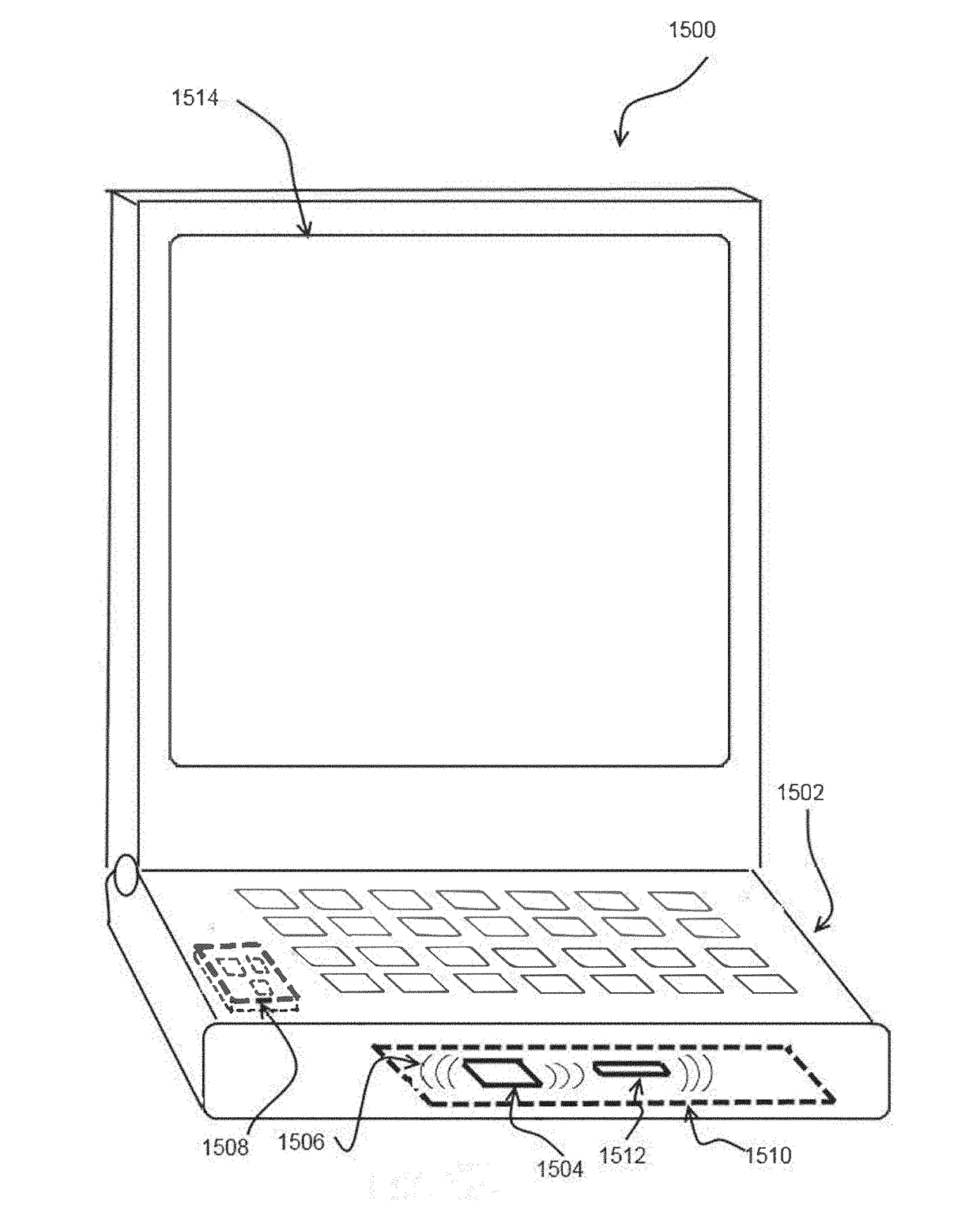
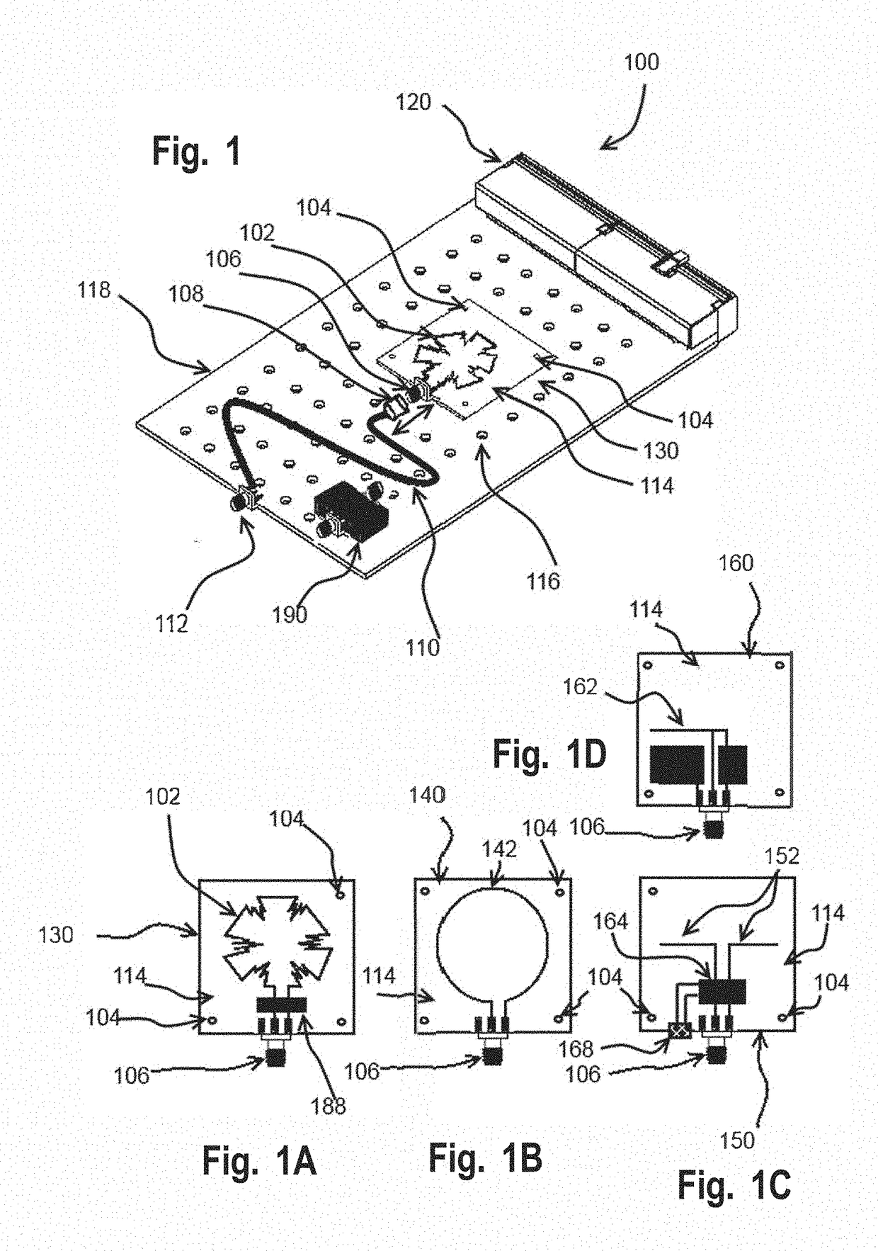
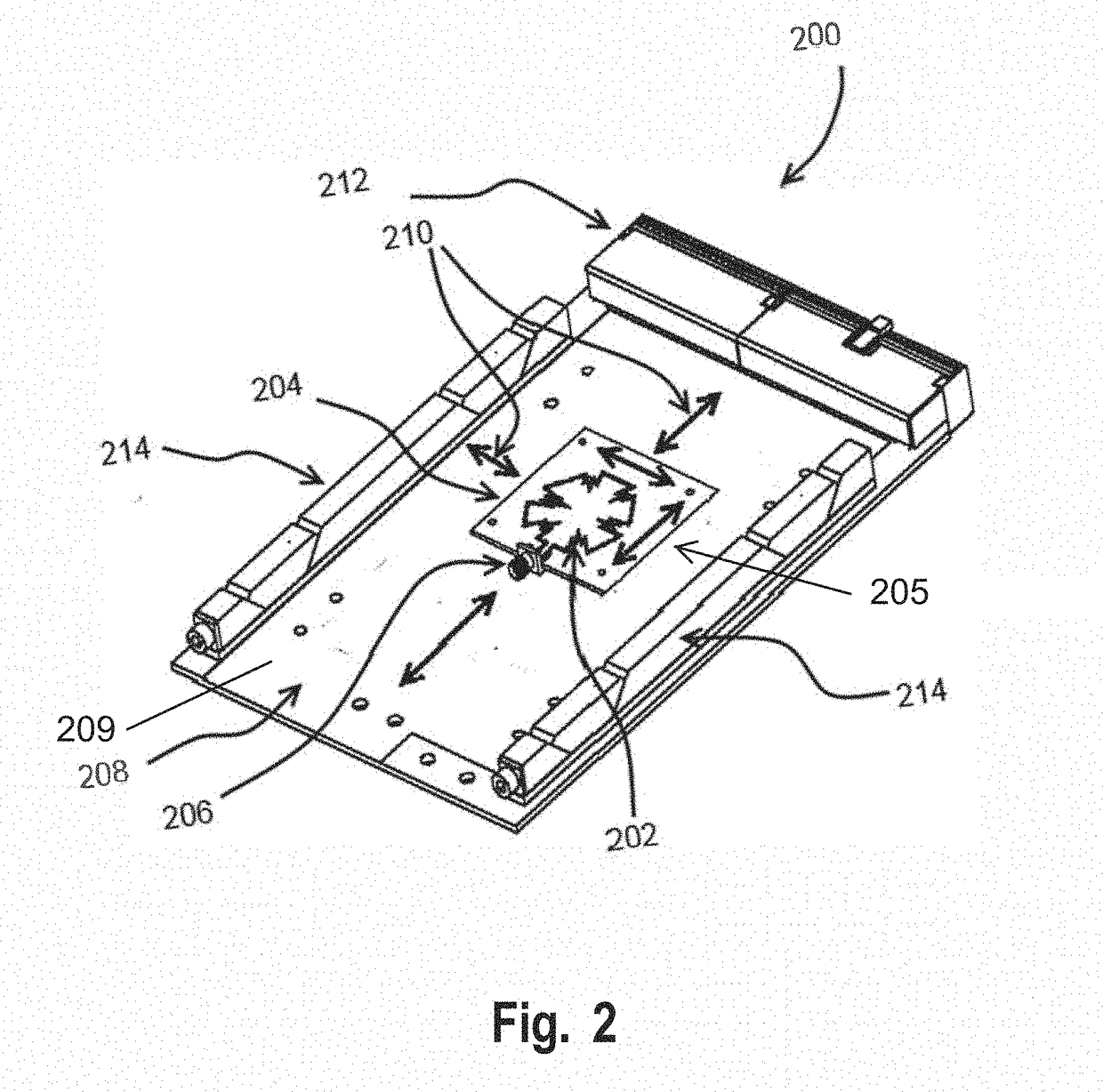
The patent is about a system and method for detecting abnormal functions in electronic cards and equipment. The system uses an antenna card that can be easily replaced with different modules that offer different RF frequency response characteristics or gain patterns. The system can detect changes, patterns, or characteristics in the intended or unintended electromagnetic emissions given off by the electrically powered devices. The system can be retrofitted into existing equipment and is not easily detected or quickly adaptable to focus on specific regions or cards of operational electronics equipment. The technical effect of this patent is to provide a more effective and efficient way to detect and diagnose operational abnormalities in electronic cards and equipment.

Problems solved by technology

This typically does not detect impending part or equipment failures which can occur before the equipment reaches the end of its Remaining Useful Life (RUL), nor does it detect failure or anomalous operation in subsections, passive components, or the whole range of electronics on a computer card.
It also is not easily retrofittable into existing equipment, especially electronics cards equipment populating a chassis and / or in a rack.
Further, it is not easily and quickly adaptable to focus on specific regions, chips, or cards of operational electronics equipment.

Method used


Image

  • Electronics card insitu testing apparatus and method utilizing unintended RF emission features
  • Electronics card insitu testing apparatus and method utilizing unintended RF emission features
  • Electronics card insitu testing apparatus and method utilizing unintended RF emission features

Examples


Embodiment Construction

[0392]The following detailed description is merely exemplary in nature and is not intended to limit the described examples or the application and uses of the described examples. As used herein, the words “example”, “exemplary” or “illustrative” mean “serving as an example, instance, or illustration.” Any implementation described herein as “example”, “exemplary” or “illustrative” is not necessarily to be construed as preferred or advantageous over other implementations. All of the implementations described below can be exemplary implementations provided to enable persons skilled in the art to make or use the embodiments of the disclosure and can be not intended to limit the scope of the disclosure, which is defined by the claims. It is also to be understood that the specific devices and processes illustrated in the attached drawings, and described in the following specification, can be simply examples of the inventive concepts defined in the appended claims.

[0393]The terms and words ...


PUM


Abstract

A diagnostic apparatus for analysis, testing, inspecting and / or screening an integrated and assembled electrically powered equipment rack and its populated cards and devices for measurement of degree of device aging, improper operation, degradation, condition, and / or Remaining Useful Life (RUL). The device includes an antenna card with a detachably attachable antenna module that can be positioned at a distance from the electrically devices under test and a signal receiver or sensor for examining a signal from the electrically powered device, but especially applied to rackmount supported electronics and / or chassis based electronics. The receiver or sensor collects unintended and / or intended RF energy components emitted by the electrically powered device and performs the above analysis in a response to the acquired signal input while the electrically powered device is active or powered.

Description

CROSS REFERENCE TO RELATED APPLICATIONS[0001]The present non-provisional application is related to and claims benefit of and priority from provisional U.S. patent application Ser. No. 62 / 490,281, titled “Electronics card insitu testing apparatus and method utilizing unintended RF emission features” and filed on Apr. 26, 2017 by Applicant Nokomis Inc., the entire contents of which are hereby incorporated by reference thereto. This present non-provisional application is also related to a co-pending non-provisional application Ser. No. 15 / 963,232, titled “Electronics equipment testing apparatus and method utilizing unintended RF emission features”, which is incorporated hereby in its entirety by reference thereto.[0002]This document incorporates by reference the entire contents of disclosures and / or teachings of the following documents: U.S. Pat. No. 7,515,094 entitled “Advanced electromagnetic location of electronic equipment”; U.S. Pat. No. 8,063,813 entitled “Active improvised explo...

Claims


Application Information

Patent Timeline
Patent Type & Authority Applications(United States)
IPC IPC(8): H01Q1/22H01Q1/38H01Q3/02H01Q1/24
CPCH01Q1/2275H01Q1/38H01Q3/02H01Q1/247G01R31/002
Inventor KELLER, III, WALTER J.
Owner NOKOMIS
Learn More