Stator of a submersible linear electric motor and method for assembling said stator

a linear electric motor and stator technology, applied in the field of electric engineering, can solve the problems of affecting becoming displaced, and reducing the efficiency so as to increase the durability of the submersible electric motor and the efficiency of its operation. , the effect of reducing the radial stress

Active Publication Date: 2018-11-01
OILFIELD EQUIP DEVMENT CENT
View PDF2 Cites 1 Cited by
  • Summary
  • Abstract
  • Description
  • Claims
  • Application Information

AI Technical Summary

Benefits of technology

[0005]The technical result achieved by implementing the claimed invention consists in increased durability of the submersible electric motor and the efficiency of its operation as a result of reduced radial stress.

Problems solved by technology

The disadvantage of the prototype is that while assembling stator, the magnetically conductive cups and support elements are centered in the housing according to their outer diameter.
Moreover, due to the engineering tolerances of the radial dimensions of the magnetically conductive cups, they become displaced relative to the axial line of the electric motor.
This gives rise to significant radial stress, which adversely affects the durability of the submersible electric motor and the efficiency of its operation.

Method used


Image

  • Stator of a submersible linear electric motor and method for assembling said stator
  • Stator of a submersible linear electric motor and method for assembling said stator
  • Stator of a submersible linear electric motor and method for assembling said stator

Examples


Embodiment Construction

Brief Description of the Drawings

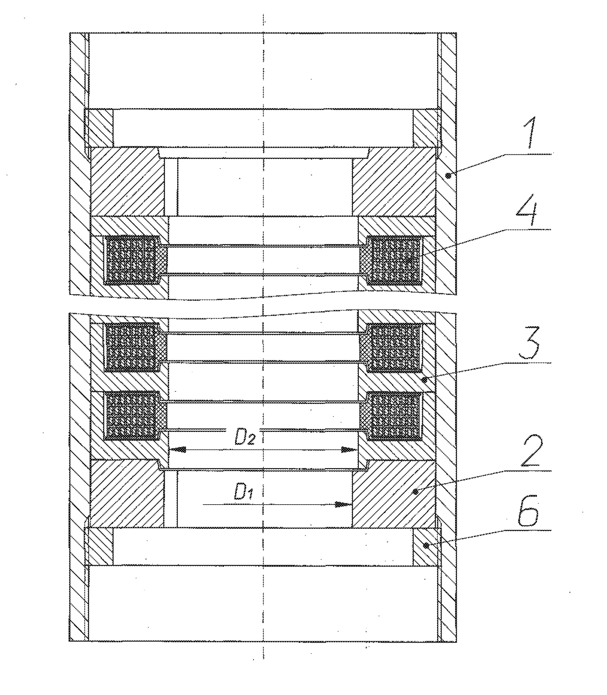
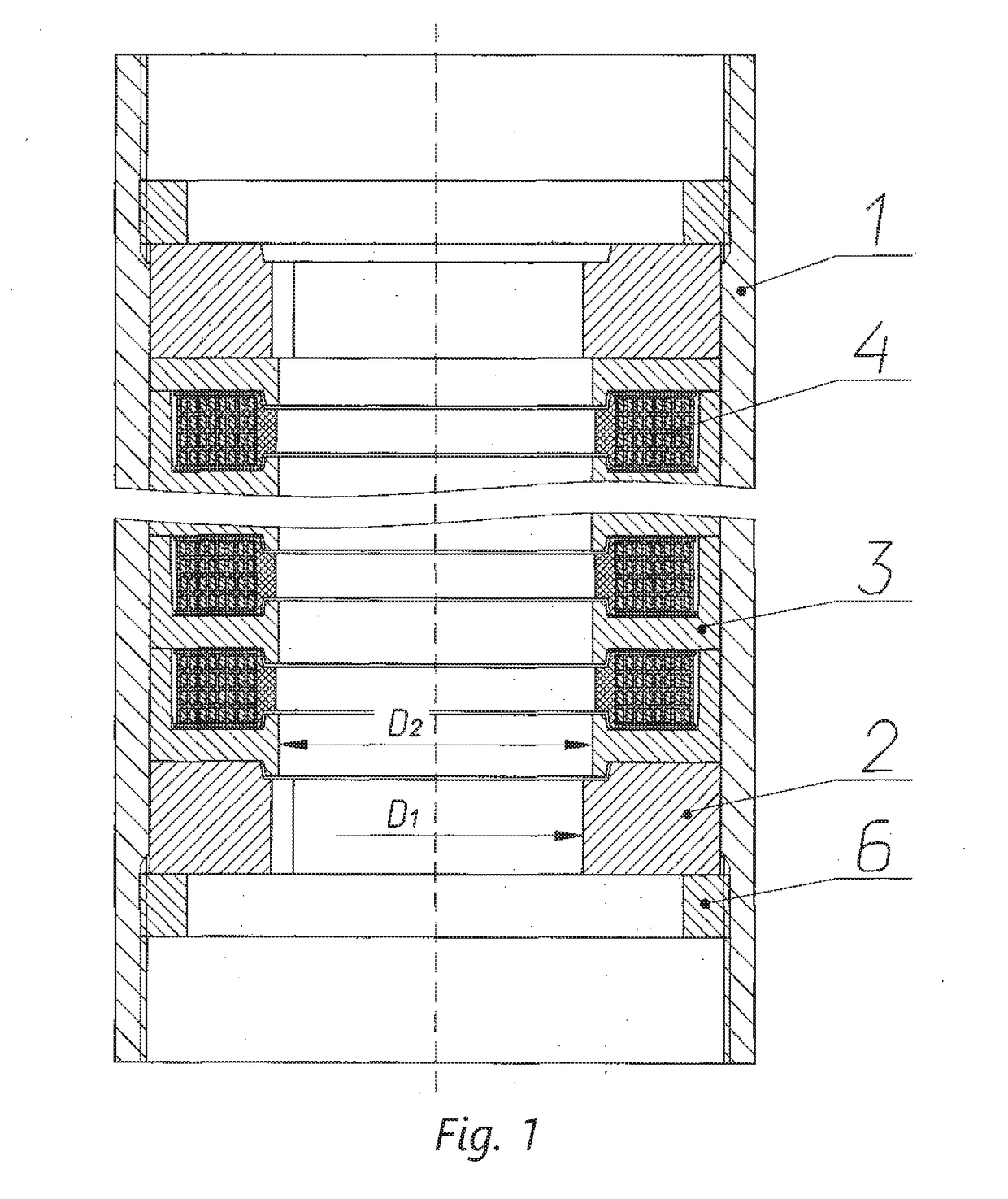
[0008]FIG. 1 shows a longitudinal section of the stator;

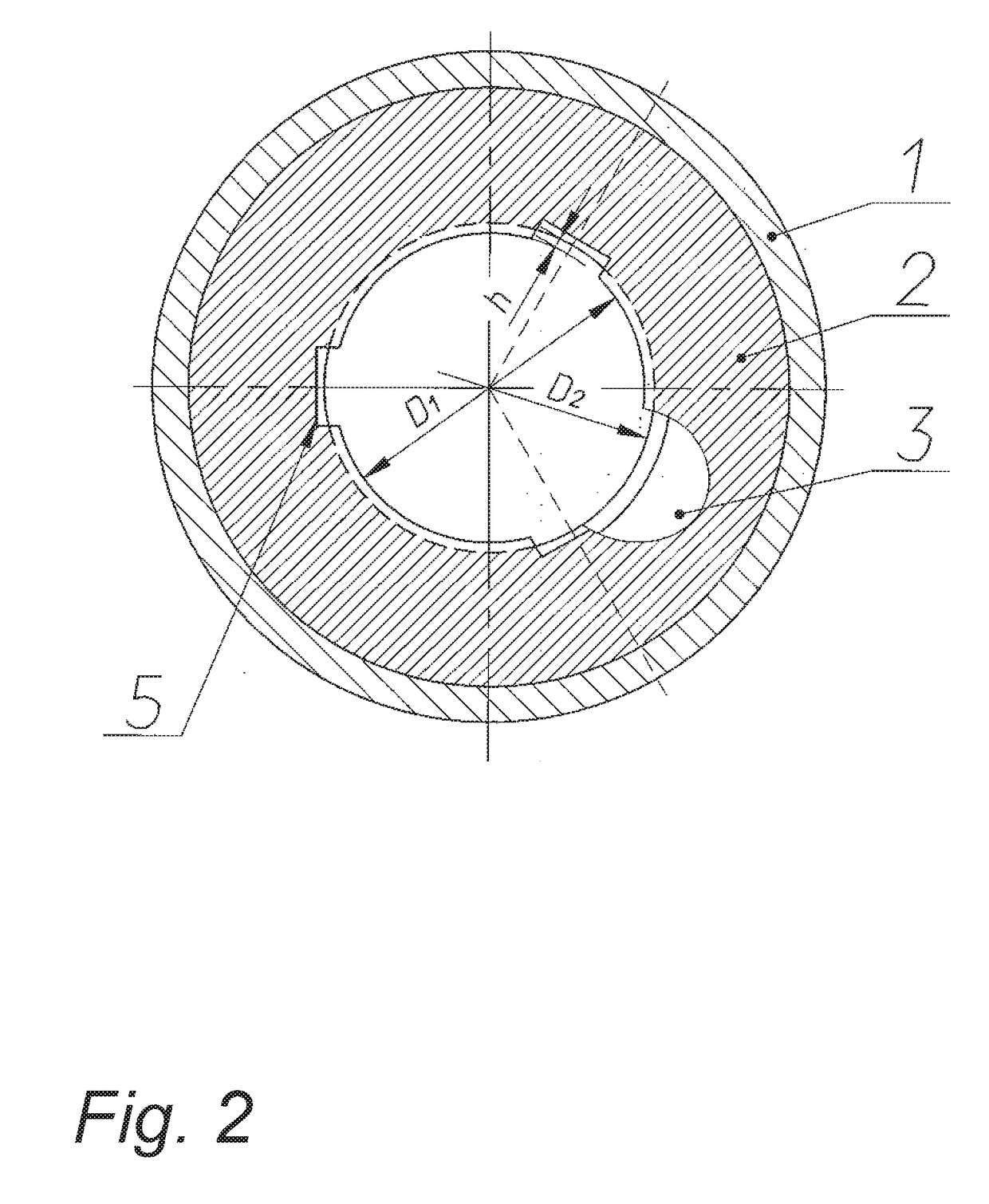
[0009]FIG. 2 is a cross-sectional view of the stator along a support element;

[0010]FIG. 3 shows a cross section of the stator with a mandrel.

[0011]The stator consists of a cylindrical housing 1, in which support elements 2 for a reciprocating head (not shown in the drawing) are installed, and magnetically conductive stator 3 cores, within which the armature coils 4 are located. The inner diameter of the magnetically conductive cores D1 is greater than the inner diameter of the support elements D2. The support elements 2 and the magnetically conductive cores 3 are attached in the housing 1 by fastening elements 6 provided in the form of threaded parts placed at its ends.

[0012]On the inner surface of the support elements 2, grooves 5 are provided, whose depth (h) is more than half the difference between the inner diameters D1 and D2.

[0013]When assembling the stator, a mandrel 7, provided in the fo...


PUM


Abstract

The invention relates to the field of electrical engineering, in particular the design of linear electric motors for submersible installations with a plunger pump, and used for oil extraction. The technical result is to increase the durability of the submersible electric motor and the efficiency of its operation. The stator consists of a cylindrical housing, within which are installed magnetically conductive cups incorporating armature coils and support elements separating the groups of cups, whereby the inner diameter of which is less than the inner diameter of the magnetically conductive cups. On the inner surface of the support elements, grooves are provided, the depth of which is more than half the difference between the inner diameters of the magnetically conductive cups and the support elements. Moreover, the magnetically conductive cups and the support elements are installed in a housing with a radial clearance and are attached therein by fastening elements.

Description

TECHNICAL FIELD[0001]The invention relates to the field of electrical engineering, in particular the design of linear electric motors for submersible installations with a plunger pump, and used for oil extraction.PRIOR ART[0002]Prior art teaches a stator of a submersible linear electric motor, consisting of a cylindrical housing within which are installed magnetically conductive cups incorporating armature coils and support elements separating the groups of cups, the inner diameter of the support elements being less than the inner diameter of the cups. The stator is assembled by installing the groups of cups with armature coils and support elements inside the cylindrical housing, followed by their fixation (see utility model RU 114240 UI, publ. Mar. 10, 2012, H02K 41 / 02).[0003]The said design of the stator for a submersible linear electric motor and its method of assembly are selected as prototype.[0004]The disadvantage of the prototype is that while assembling stator, the magnetica...

Claims


Application Information

Patent Timeline
Patent Type & Authority Applications(United States)
IPC IPC(8): H02K15/02H02K41/02H02K5/132H02K1/18
CPCH02K15/02H02K41/02H02K5/132H02K1/185
Inventor SAGALOVSKY, VLADIMIR IOSIFOVICHSAGALOVSKY, ANDREY VLADIMIROVICH
Owner OILFIELD EQUIP DEVMENT CENT
Why Eureka
Try Eureka