Image stabilization apparatus, control method thereof, and storage medium
a technology of image stabilization and control method, which is applied in the field of image stabilization apparatus, can solve the problems of increasing the size of the apparatus, increasing power consumption, and inability to perform image blur correction for the remaining one axis, and achieves the effect of high image blur correction
- Summary
- Abstract
- Description
- Claims
- Application Information
AI Technical Summary
Benefits of technology
Problems solved by technology
Method used
Image
Examples
first embodiment
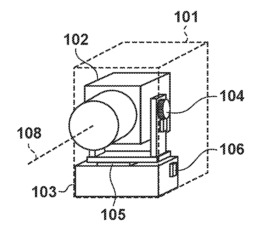
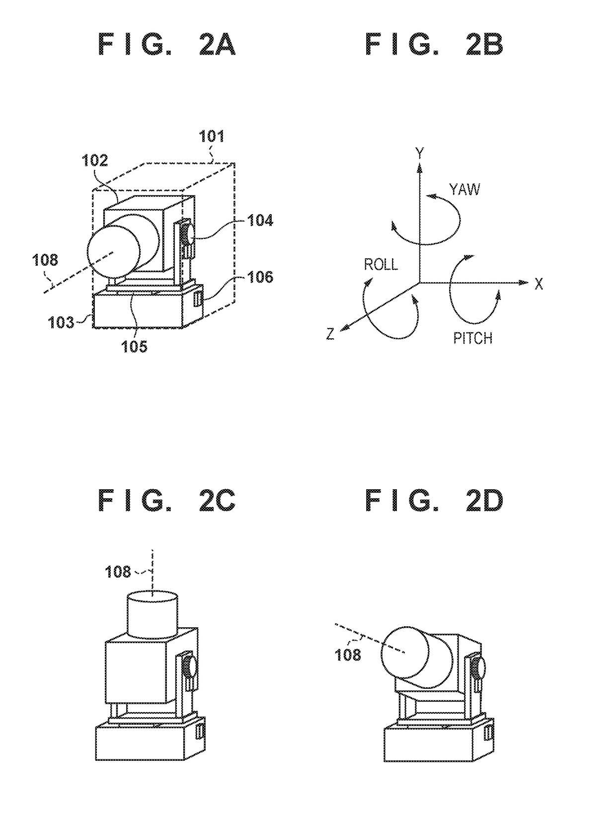
[0033]FIGS. 2A to 2D are diagrams schematically showing a camera 101 as a first embodiment of an image capturing apparatus of the present invention. The camera 101 shown in FIG. 2A is provided with a power switch, operation members that can perform camera operations, and the like. A barrel 102 that integrally includes a shooting lens group as an imaging optical system that performs image capturing and an image sensor is attached to the camera 101. Furthermore, the camera 101 has a mechanism that makes it possible to rotationally drive (rotate) the barrel 102 relative to a fixing unit (main body unit) 103.
[0034]A tilt rotation unit 104 has a motor driving mechanism that can rotationally drive the barrel 102 in a pitch direction shown in FIG. 2B, and a pan rotation unit 105 has a motor driving mechanism that can rotationally drive the barrel 102 in a yaw direction shown in FIG. 2B. Accordingly, the camera 101 has a mechanism for rotationally driving the barrel 102 in two axis directio...
second embodiment
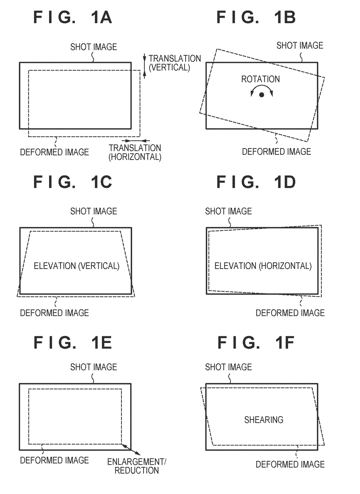
[0104]In the first embodiment, a method for changing correction limit values for translation, elevation, and rotation from among electronic image blur corrections based on tilt angle has been described, but a configuration may be adopted in which rolling shutter distortion correction is included. In a second embodiment, setting of limit values for the respective types of correction including rolling shutter distortion correction and a control method thereof will be described.
[0105]In recent years, in image capturing apparatuses such as digital cameras and digital video cameras, a CMOS sensor whose power consumption is lower than a CCD has often been used as an image sensor. Not only that a CCD and a CMOS sensor are different in power consumption, but also exposure methods during shooting are different. When capturing one (captured) image, exposure timings and exposure periods in all the pixels of the image sensor in a CCD are the same, while in a CMOS sensor, the shutter opening / clo...
third embodiment
[0123]In the first and second embodiments, an operation of changing correction limit values for translation, elevation, rotation, rolling shutter distortion and the like in electronic correction according to a tilt angle has been described. However, regarding an axis about which mechanical correction cannot be performed, if an amount of shake about the same axis is small, it is not necessary to set a limit value for an electronic correction amount about this axis to be large. In the third embodiment, a method for setting electronic correction limit values according to the magnitude of shake amounts about axes relative to the imaging plane, in addition to a tilt angle, will be described.
[0124]FIG. 17 is a diagram for explaining a method for calculating limit values in the limit value calculation unit 508 in the block diagram in FIG. 8 of the first embodiment. In addition to a tilt angle, mechanical residual correction angular speeds (PitchErr, YawErr, and RollErr) that are outputs of...
PUM
 Abstract
Description
Claims
Application Information
 - R&D
- Intellectual Property
- Life Sciences
- Materials
- Tech Scout
- Unparalleled Data Quality
- Higher Quality Content
- 60% Fewer Hallucinations
Browse by: Latest US Patents, China's latest patents, Technical Efficacy Thesaurus, Application Domain, Technology Topic, Popular Technical Reports.
© 2025 PatSnap. All rights reserved.Legal|Privacy policy|Modern Slavery Act Transparency Statement|Sitemap|About US| Contact US: help@patsnap.com


