
Speaker driver with aligned features

Inactive Publication Date: 2018-11-01
BELLAS KIMON
View PDF6 Cites 1 Cited by
  • Summary
  • Abstract
  • Description
  • Claims
  • Application Information

AI Technical Summary

Benefits of technology

The present disclosure is about improving speaker drivers to make them more efficient. The drivers reduce the buildup of inductance and modulation, and also reduce air pressure in the device. This promotes air flow to lower the temperature of all components. Overall, the patent provides a better way to design speaker drivers to improve performance.

Problems solved by technology

This back-and-forth, oscillatory motion drives the air in the device, which results in pressure differentials that convert to sound waves.
There are several problems that traditional speaker drivers can encounter, as a result of the aforementioned oscillatory motion.
Yet within the speaker driver there is little room for cooling components or other options to reduce the temperature.
The resulting heat increase can cause a variety of component problems, such as voice coil resistance increase that reduces sensitivity and causes compression.
Excessive heat will cause component failure.
Additionally, some of the air caused by the aforementioned oscillatory motion can become trapped within the speaker driver.
This can cause a variety of unwanted side effects, such as resonance and / or noise.
Moreover, inductance buildup and inductance modulation is another problem that frequently arises in speaker drivers.
Among other side effects, inductance modulation can cause distortion and reduced efficiency in the driver.
Another common problem in speaker drivers is the existence of eddy currents, which are a localized electric currents induced by a varying magnetic field.
Furthermore, speaker drivers can also experience intermodulation distortion, which is amplitude modulation of signals containing different frequencies, often caused by nonlinearities.
Each of these issues present efficiency problems for speaker drivers.

Method used


Image

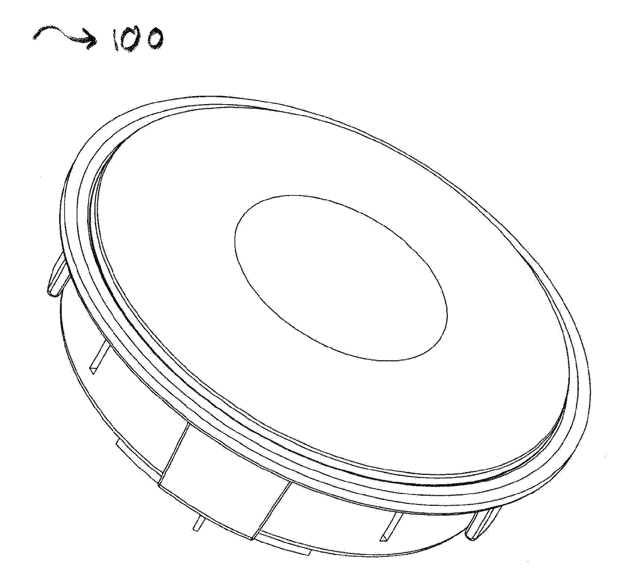
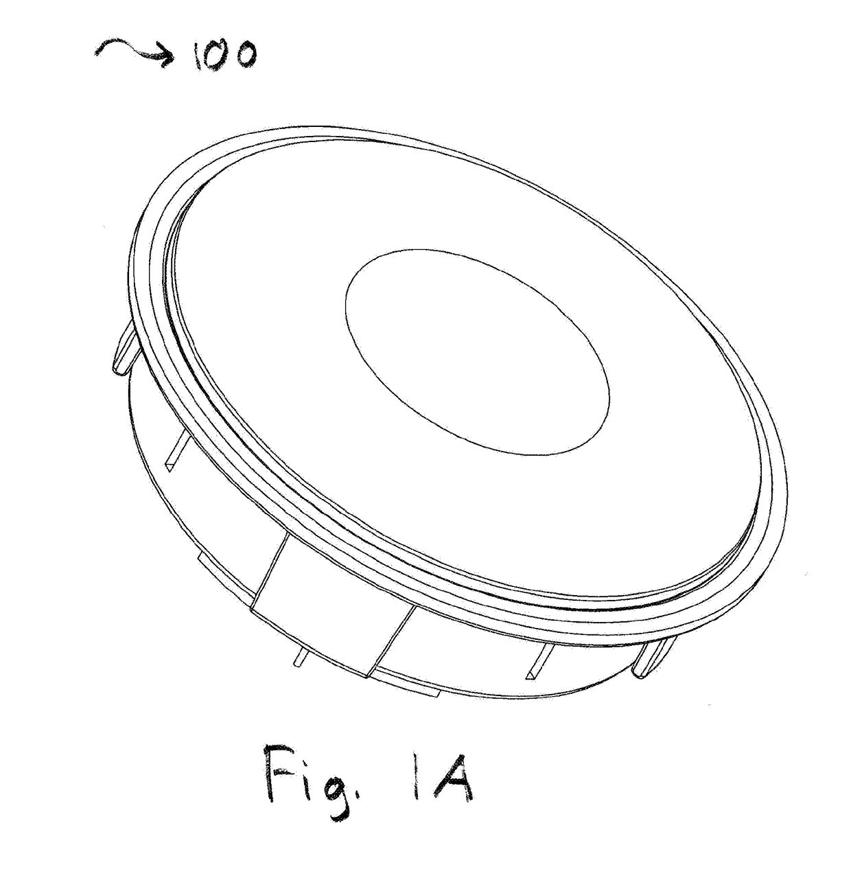
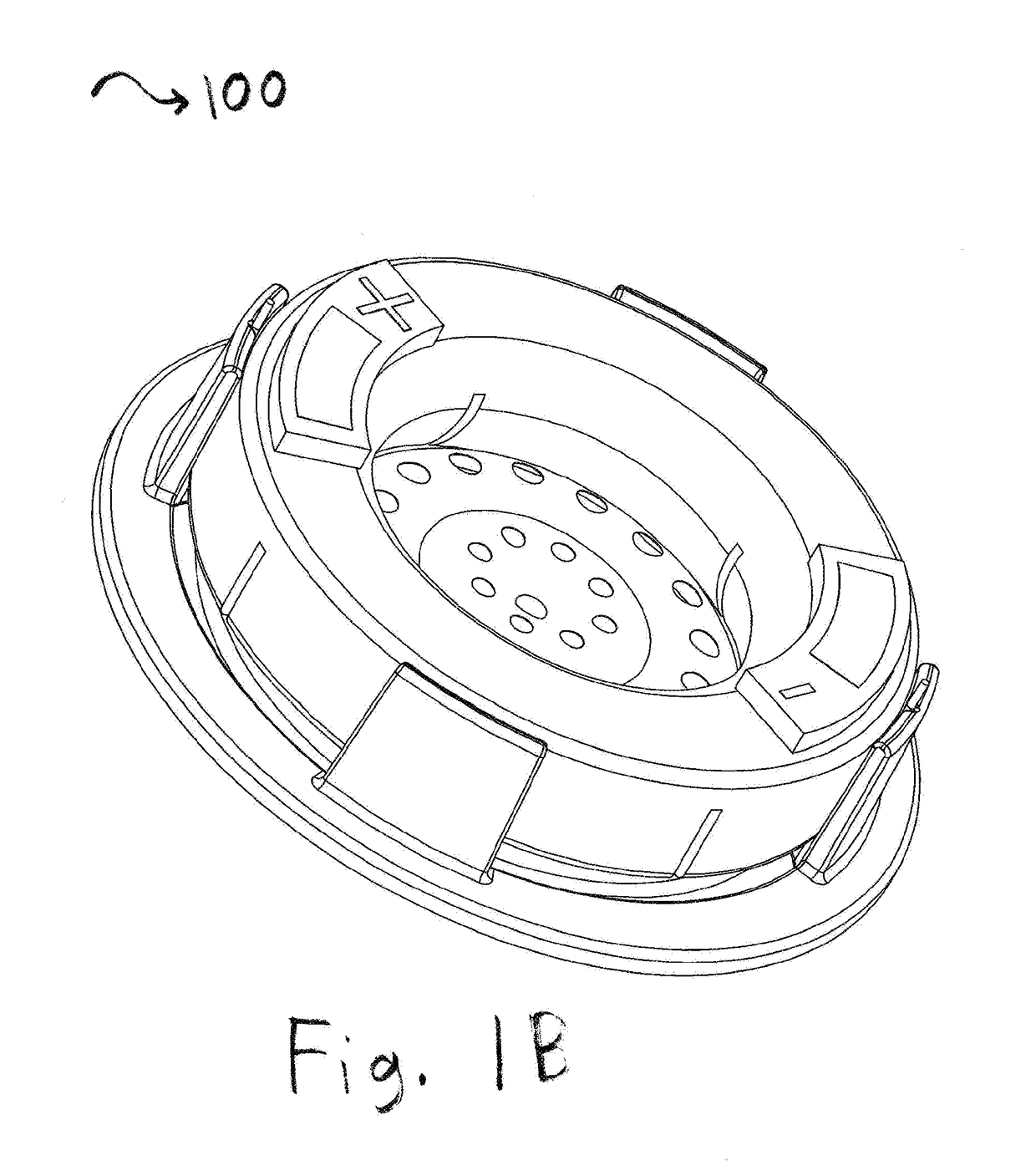
  • Speaker driver with aligned features
  • Speaker driver with aligned features
  • Speaker driver with aligned features

Examples


Embodiment Construction

[0085]Devices and methods described herein can comprise novel and improved designs and layouts to optimize the efficiency in speaker drivers. Embodiments of the present disclosure can also include a speaker driver comprising novel and improved slot and / or gap designs. Some embodiments according to the present disclosure can optimize the efficiency of the speaker driver through the alignment of slots and / or gaps. By doing so, the air flow throughout the speaker driver can be optimized. Slots and / or gaps can be present in magnets, base cups, and / or any other component in the motor assembly of the speaker driver. Utilizing the novel and improved designs and layouts described herein, speaker drivers according to the present disclosure can have a wide array of advantages, including but not limited to the reduction of inductance buildup and inductance modulation, the reduction of air pressure, the reduction of component temperature and / or the promotion of increased air flow.

[0086]Speaker ...


PUM


Abstract

Devices and methods described herein can comprise novel and improved designs and layouts to optimize the efficiency in speaker drivers. Embodiments of the present disclosure can include a speaker driver comprising novel and improved slot and / or gap designs. Some embodiments according to the present disclosure can optimize the efficiency of the speaker driver through the alignment of slots and / or gaps. By doing so, the air flow throughout the speaker driver can be optimized. Slots and / or gaps can be present in magnets, base cups, and / or any other component in the motor assembly of the speaker driver. Utilizing the novel and improved designs and layouts described herein, speaker drivers according to the present disclosure can have a wide array of advantages, including but not limited to the reduction of inductance buildup, reduction of inductance modulation, the reduction of air pressure, and / or the promotion of increased air flow and reduced operating temperatures.

Description

BACKGROUNDField[0001]The present disclosure relates generally to audio transducers and / or speaker drivers, and more particularly to novel and improved speaker drivers having aligned features and improved air flow.Description of the Related Art[0002]Speaker drivers are a type of audio transducer that convert electrical audio signals to sound waves. Speaker drivers are commonly associated with specialized transducers, which can reproduce a portion of the audible frequency range. Additionally, speaker drivers are sometimes referred to as loudspeakers.[0003]A common type of speaker driver, often referred to as a dynamic or electrodynamic driver, converts electric current to sound waves via a coil of wire. This is widely known as a voice coil, which is often suspended between magnetic poles. During operation, a signal is delivered to the voice coil by means of electrical wires. This current flowing in the voice coil creates a magnetic field that causes a component, such as a diaphragm, t...

Claims


Application Information

Patent Timeline
IPC IPC(8): H04R9/06H04R1/10H04R7/12H04R9/02
CPCH04R9/06H04R1/1008H04R2460/11H04R7/127H04R9/025H04R1/1075H04R9/04H04R9/022H04R9/046H04R2209/021
Inventor BELLAS, KIMONHULSEBUS, II, ALAN DWIGHT
Owner BELLAS KIMON
Learn More