Camera module

Active Publication Date: 2018-11-08
LG INNOTEK CO LTD
View PDF3 Cites 0 Cited by
  • Summary
  • Abstract
  • Description
  • Claims
  • Application Information

AI Technical Summary

Benefits of technology

The invention is a camera module that has a reinforcement portion to prevent separation between the lens driving device and the first circuit board, even when an external force is applied. This prevents deformation of the second circuit board, which can lead to damage or cracks at the circuit pattern. The camera module has a structure that covers an exposed area of the second terminal, and a reinforcement portion can also prevent damage or cracks from occurring at the circuit pattern formed across the first terminal, second terminal, and second circuit board. This invention ensures high-quality and resolution images can be captured without any issues caused by separation between the lens driving device and the first circuit board.

Problems solved by technology

In particular, when the lens driving device is separated from the circuit board, the lens driving device cannot properly perform the auto-focusing function, and thus the resolution of the image captured by the camera module may also be degraded.
If the flexible portion of the circuit board repeatedly deforms due to continuous external forces, it may cause cracks and damages to the circuit patterns, terminals and the like included in the circuit board, and the cracks and damages may cause malfunction of the camera module.

Method used


Image

  • Camera module
  • Camera module
  • Camera module

Examples


Embodiment Construction

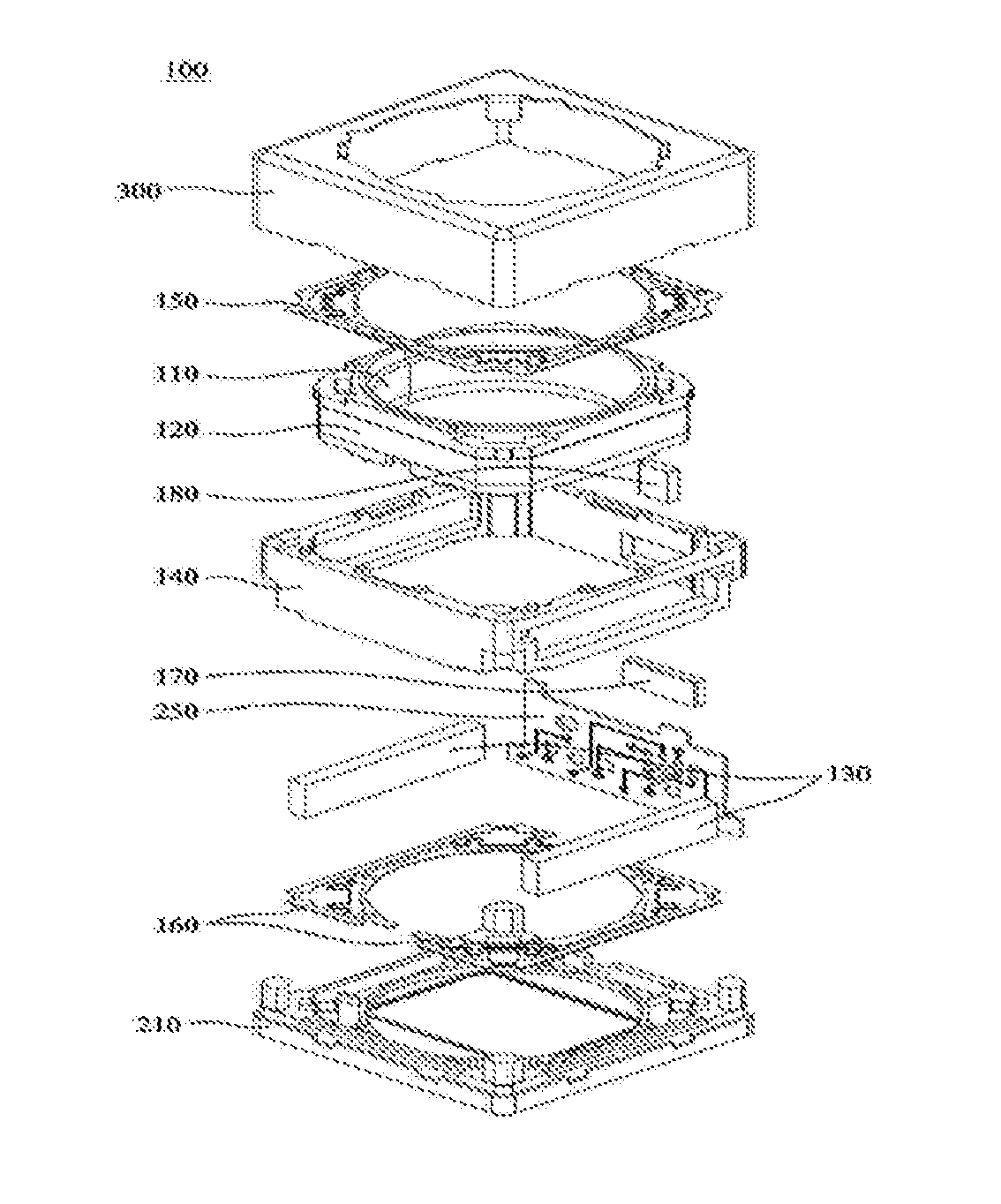
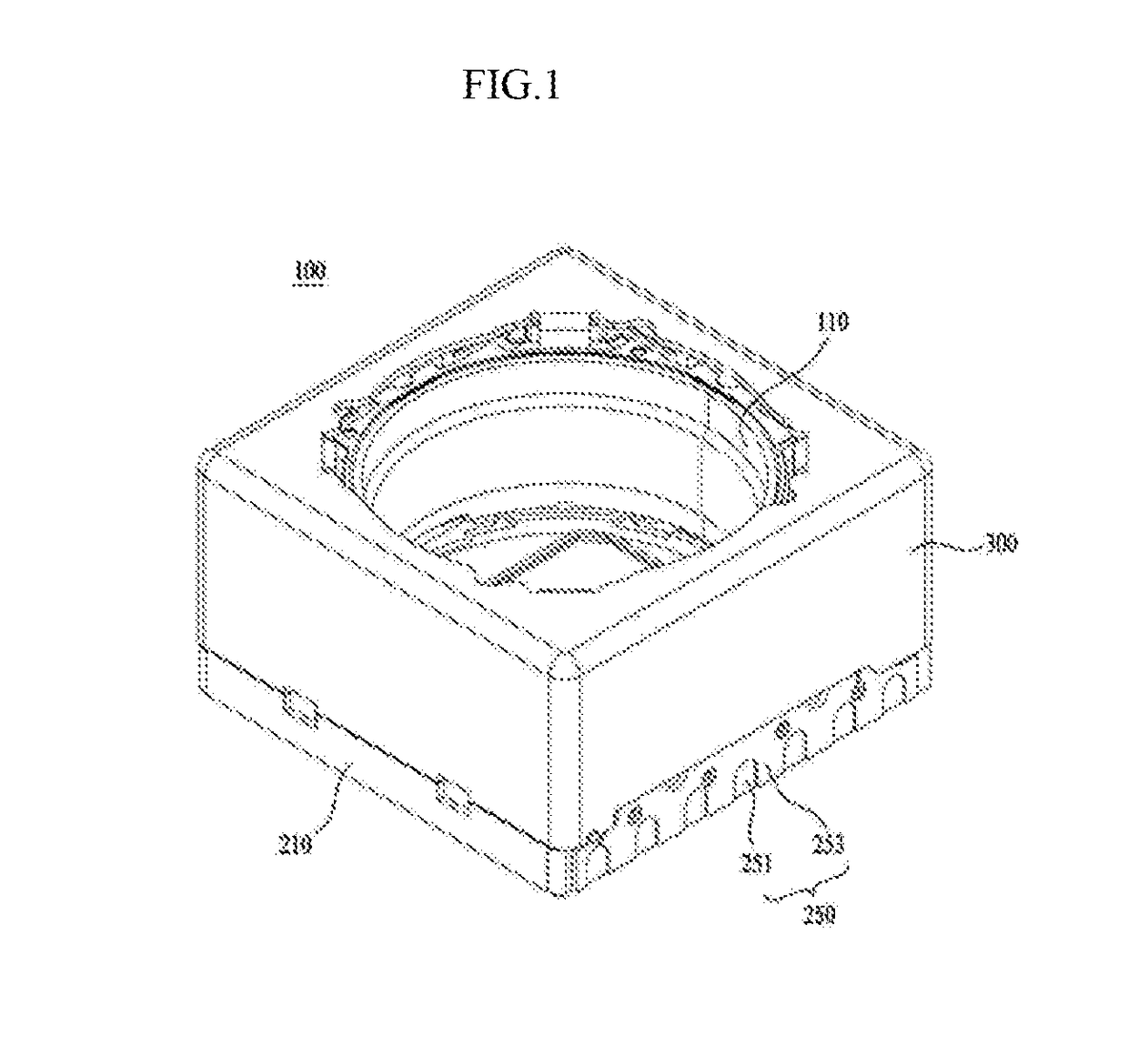
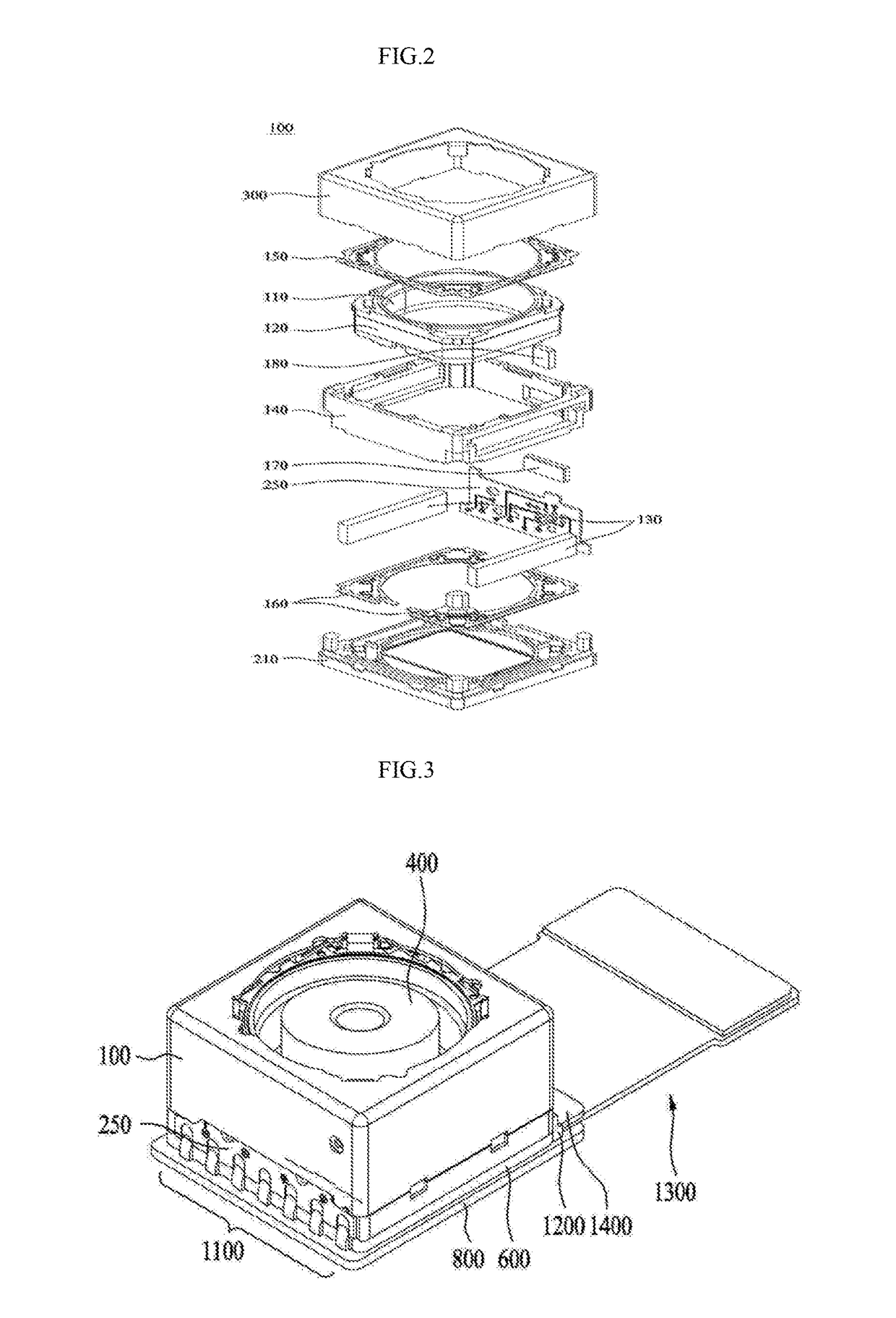
[0033]Reference will now be made in detail to the preferred embodiments, examples of which are illustrated in the accompanying drawings. While the embodiments are susceptible to various modifications and alternative forms, specific embodiments thereof are shown by way of example in the drawings. However, the invention should not be construed as limited to the embodiments set forth herein, but on the contrary, the invention is to cover all modifications, equivalents, and alternatives falling within the spirit and scope of the embodiments. In the drawings, sizes and shapes of elements may be exaggerated for convenience and clarity of description.

[0034]It may be understood that, although the terms “first,”“second,” etc. may be used herein to describe various elements, these elements are not to be limited by these terms. The terms are generally used to distinguish one element from another. In addition, terms particularly defined in consideration of the construction and operation of the ...


PUM


Abstract

A camera module of an embodiment may comprise: a first holder in which a filter is mounted; a lens barrel which is provided to be vertically movable in a first direction with respect to the first holder; a lens operating device which comprises a terminal and moves the lens barrel in the first direction; a first circuit board which is disposed under the first holder and on which an image sensor is mounted; a soldering part for electrically connecting the terminal of the lens operating device to the first circuit board; and a coupling reinforcement part which is disposed to face the soldering part and couples the lens operating device and the first circuit board.

Description

TECHNICAL FIELD[0001]Embodiments relate to a camera module.BACKGROUND ART[0002]The statements in this section merely provide background information related to the embodiments and may not constitute prior art.[0003]In recent years, IT devices such as a mobile phone with a camera installed therein, a smart-phone, a tablet PC, a laptop computer, etc. have been actively developed.[0004]In the case of a camera module mounted in a small electronic device such as a smart-phone, the camera module may include a device for auto-focusing. Specifically, a lens driving device for auto-focusing and a circuit board that is coupled to the lens driving device and accommodates an image sensor can be provided in the camera module.[0005]Meanwhile, if an external force is applied to the camera module, the lens driving device may be separated from the circuit board. If the lens driving device and image sensor are separated from each other, the quality of an image captured by the camera module may be degr...

Claims


Application Information

Patent Timeline
IPC IPC(8): H04N5/225G02B7/00H05K1/03G02B7/09
CPCH04N5/2254G02B7/006H05K1/0306G02B7/09H05K2201/10151H05K2201/0175G03B13/36G03B5/00G02B7/08G02B27/646H05K3/305H05K2201/09036H05K1/147H05K3/341H05K1/0281H05K2201/10121H04N23/54H04N23/55Y02P70/50H04N23/57H05K1/181
Inventor CHUNG, JONG HOLEE, SUNG IL
Owner LG INNOTEK CO LTD
Why Eureka
Try Eureka