Image forming apparatus and image forming method

a technology of image forming apparatus and liquid absorbing member, which is applied in the direction of duplicating/marking methods, inks, printing, etc., can solve the problems of image smearing, image smearing, and image smearing, etc., and achieve the effect of high absorption

Active Publication Date: 2018-11-15
CANON KK
View PDF0 Cites 9 Cited by
  • Summary
  • Abstract
  • Description
  • Claims
  • Application Information

AI Technical Summary

Benefits of technology

[0008]However, depending on liquid absorbency of the liquid absorbing member or forming conditions of the nip part, there may be a case where smeared image may occur during treatment by the liquid absorbing member or an intended liquid removing effect from the image by the liquid absorbing member may not be obtained.
[0009]An object of the present invention is to provide an image forming apparatus and an image forming method capable of achieving high absorption and removal of a liquid component from an image without disturbing an image by contacting a liquid absorbing porous body with the image including the liquid component.

Problems solved by technology

However, depending on liquid absorbency of the liquid absorbing member or forming conditions of the nip part, there may be a case where smeared image may occur during treatment by the liquid absorbing member or an intended liquid removing effect from the image by the liquid absorbing member may not be obtained.

Method used


Image

  • Image forming apparatus and image forming method
  • Image forming apparatus and image forming method
  • Image forming apparatus and image forming method

Examples


example

[0189]Hereinafter, the present invention is described in more detail with reference to Examples and Comparative Examples. The present invention is not limited to the following examples, unless exceeding the gist thereof. In addition, in the following description of the Examples, “part” is based on mass unless otherwise specified.

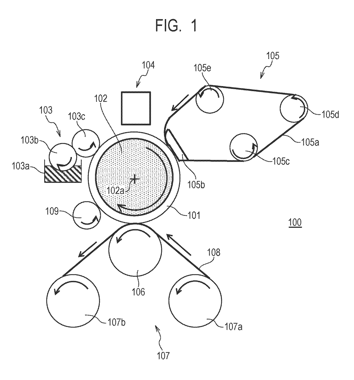
[0190]In the present Example, the transfer type ink jet printing apparatus shown in FIG. 1 was used.

The transfer body 101 of the present Example is fixed to a support member 102 with an adhesive. In the present Example, a sheet in which a PET sheet with a thickness of 0.5 mm was coated with silicone rubber (KE12, manufactured by Shin-Etsu Chemical Co., Ltd.) to have a thickness of 0.3 mm was used as an elastic layer of a transfer body J. In addition, a mixture of a condensate obtained by mixing glycidoxypropyl triethoxysilane and methyltriethoxysilane at a molar ratio of 1:1, followed by heat refluxing, and a cationic photopolymerization initiator (SP150, ma...

examples 2 to 4

[0209]In Examples 2 to 4, so as to satisfy the above-described Relational Expressions (1) to (3), curvature on an inlet side of the transfer body 101 and curvature on an outlet side were changed in a curved surface portion of the pressing member and the level was divided. Except for the above change, the image formation and evaluation of the formed image were performed in the same manner as in Example 1.

example 5

[0210]Using the pressing member in Example 3, the angle and pressure with respect to the transfer body 101 were adjusted. Except for the above adjustment, the image formation and evaluation of the formed image were performed in the same manner as in Example 1.


PUM

PropertyMeasurementUnit
pressureaaaaaaaaaa
contact pressuresaaaaaaaaaa
dispersion stabilityaaaaaaaaaa

Abstract

In a process of an ink receiving medium entering a nip part with a liquid absorbing member, force in a direction to sweep up an image to be processed as an absorption removal treatment target is reduced by changing a nip pressure of the nip part in a conveying direction of the ink receiving medium. Furthermore, when peeling off the liquid absorbing member from the ink receiving medium from the nip part, force for pulling a liquid component toward a porous body is effectively applied. As a result, it is possible to achieve high absorption and removal of the liquid component from the image to be processed while suppressing disturbance of the image to be processed.

Description

CROSS-REFERENCE TO RELATED APPLICATIONS[0001]This application is a Continuation of International Patent Application No. PCT / JP2016 / 005243, filed Dec. 28, 2016, which claims the benefit of Japanese Patent Application No. 2016-000748, filed Jan. 5, 2016, and Japanese Patent Application No. 2016-107970, filed May 30, 2016, all of which are hereby incorporated by reference herein in their entirety.BACKGROUND OF THE INVENTIONField of the Invention[0002]The present invention relates to an image forming apparatus and an image forming method.Description of the Related Art[0003]In an ink-jet printing technique, an image is formed by directly or indirectly applying a liquid composition (ink) including a coloring material onto a printing medium such as paper, or the like. Here, curl or cockling occurs due to excessive absorption of a liquid component in the ink by the printing medium.[0004]Thus, in order to quickly remove the liquid component from the ink, there is a method for drying a printi...

Claims


Application Information

Patent Timeline
Patent Type & Authority Applications(United States)
IPC IPC(8): B41J11/00B41J29/17
CPCB41J11/0015B41J29/17B41J2/01B41J29/38B41J2002/012B41M5/0256B41M7/00C09D11/322C09D11/38C09D11/40C09D11/54B41M5/50B41J2/0057
Inventor HIROKAWA, RYOSUKEYAMANE, TORUMOURI, AKIHIRO
Owner CANON KK
Why Eureka
Try Eureka